www.brian-lambert.co.uk

Digital Command Control - DCC
Page 2


Accessory Decoder.
DCC allows the use of special accessory decoders to be connected either to the DCC bus or to the rails and the decoder can then operate several accessories such as solenoid point motors, stall point motors and colour light signals etc. There are several manufactures of accessory decoders and they should be able to work with most DCC control systems, in exactly the same way loco decoders will work with any system. Some accessory decoders require a separate power supply to provide the power to operate the connected accessories while others take their power directly from the DCC bus or rails. If possible choose a decoder that uses a separate power supply, as this will not put any added loading onto the DCC control system, leaving the DCC system to run the locos.
Some accessory decoders have only fixed pulse outputs which are only suitable for powering solenoid point motors, while others (The vast majority now) offer user selectable outputs - pulse through to constant power output per set of terminals. Pulse being for Solenoid point motors while constant is suitable for stall motors or signal feeds etc. The number of outputs varies too, most provide four separate outputs as a minimum and some can provide up to eight outputs. Normally each set of outputs are in groups of three. Often marked as + C - , where + is one feed C is its Common connection and - is the opposite feed. When '+' output is turned on the '-' output is turned off and vice versa, with 'C' and the common to either.
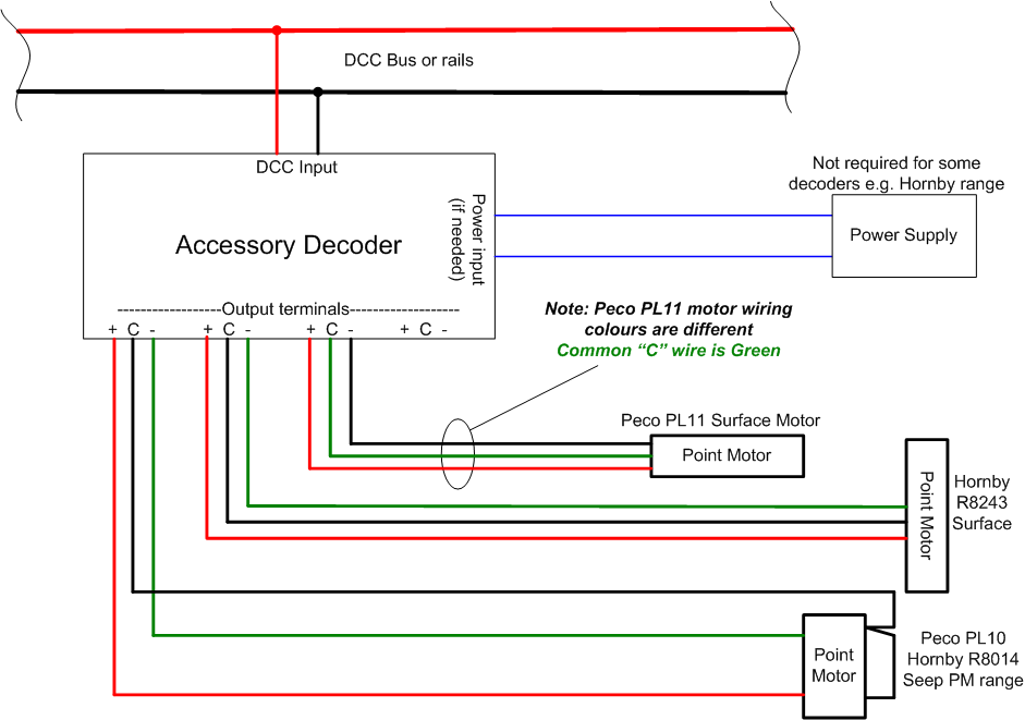
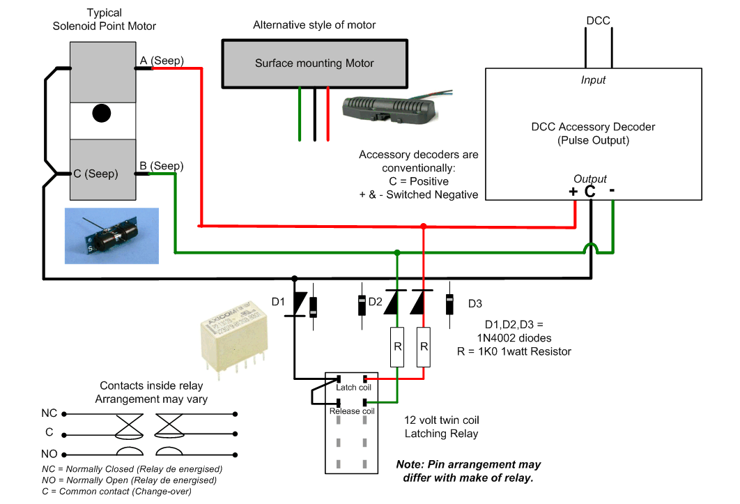
Below are shown two very basic accessory decoder installations. In the top drawing the decoder is feeding three different makes of solenoid motors. Outputs 1 to 3 are only used leaving output 4 spare.
Also note that the Peco PL11 Surface mounting motor has factory fitted wires that differ in colour from other makes - The Peco PL11 uses Green as the Common and Red & Black as the motors feeds.
Where any motor throws the wrong way to that expected, swap the + and - wires around on the appropriate output terminals.
In the lower drawing a variable output accessory decoder is shown where the outputs can be individually set from a short duration pulse of a few milliseconds (ideal for solenoid point motors etc to continuously on for powering LEDs, filament lamps or stall style point motors etc.
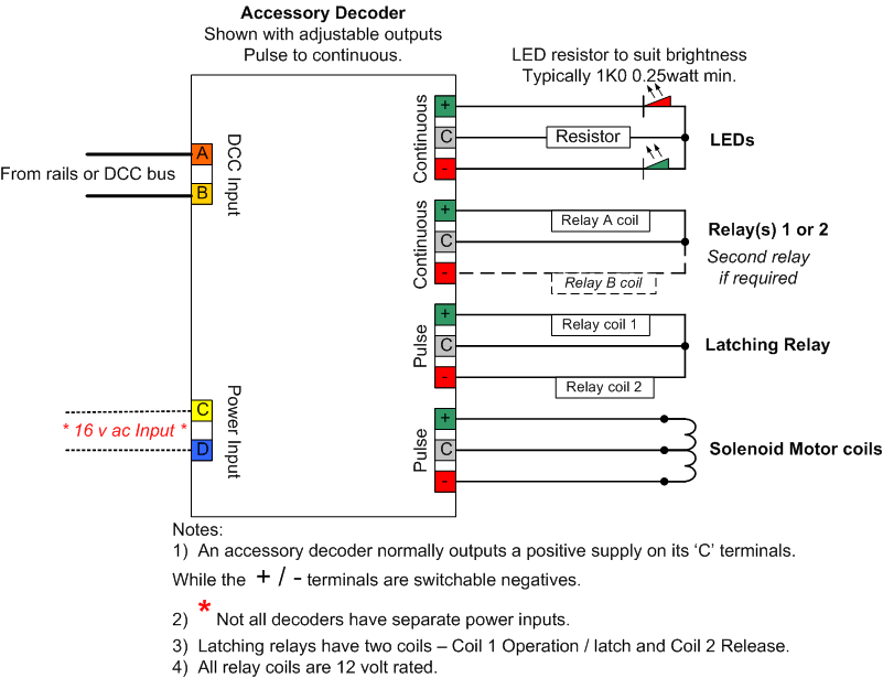
In the example above Output 1 is shown feeding typically a two aspect colour light signals LEDs Note these MUST be common Positive feed. Output 2 is shown operating a 12 volt relay coil or two relays if both outputs of No2 are used. The relay contacts can then switch larger powered items or provide multiple switching as required. Output 3 feeds one 'Latching' relay. The latch relay is operated and held operated by a momentary pulse of power to its latching coil 1.. The opposite output, which is also a pulse operates momentarily the Release coil of the relay. Output 4 is shown operating a standard solenoid motor coils and is also a Pulse output.
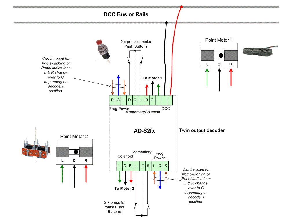
Below shows a DCC Concepts AD-S2fx or the larger AD-S4fx or AD-S8fx solenoid accessory decoders which offer simple DCC setting up and one Capacitor Discharge Unit for each of its outputs. Below is a wiring diagram for the AD-S2fx. Note that the AD-S4fx and the larger AD-S8fx are identical and only require one DCC input, even though there are two or four DCC input connections available. Easier to remember is that the AD-S4 or 8fx is just two or four AD-S2fx on one larger circuit board. The DCC input connections are linked through on the circuit board of the AD-S4/8fx. All three decoder variants offer the option of adding press button point operation and an electrically separate change-over set of contacts that can be used for frog switching or LED panel indications.
Below shows how to use a 12 volt Twin coil latching relay with an Accessory Decoder set to Pulse output to drive solenoid point motor.
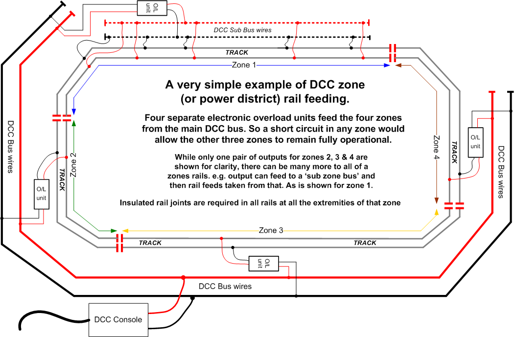
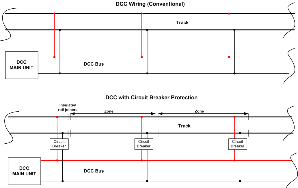
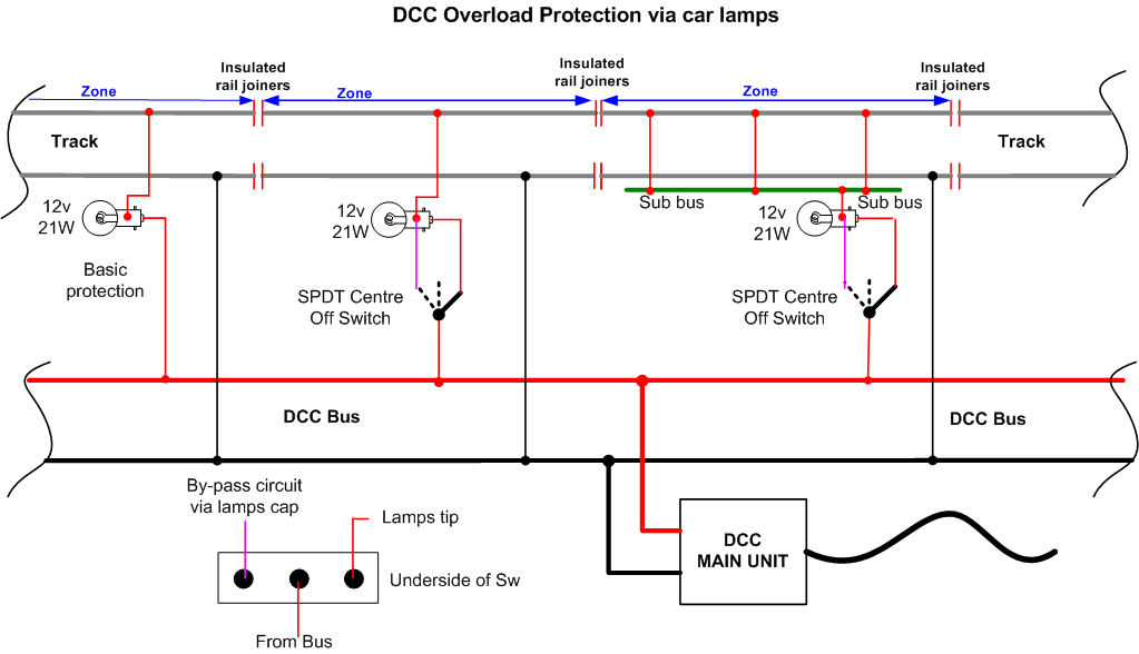
The simplified diagrams below show in the upper drawing a conventional DCC bus and supplies to rails and in the lower drawing the same layout with the use of the Circuit Breaker zonal trips and insulated rail joiners installed to make up the protected zones. Of course, in reality the zones would control a much larger area of track than shown in the simple examples below. A typical example is:- The whole station area on one zone and the goods yard and sidings area on another. Therefore a short circuit occurring in the goods yard won’t effect the main lines.
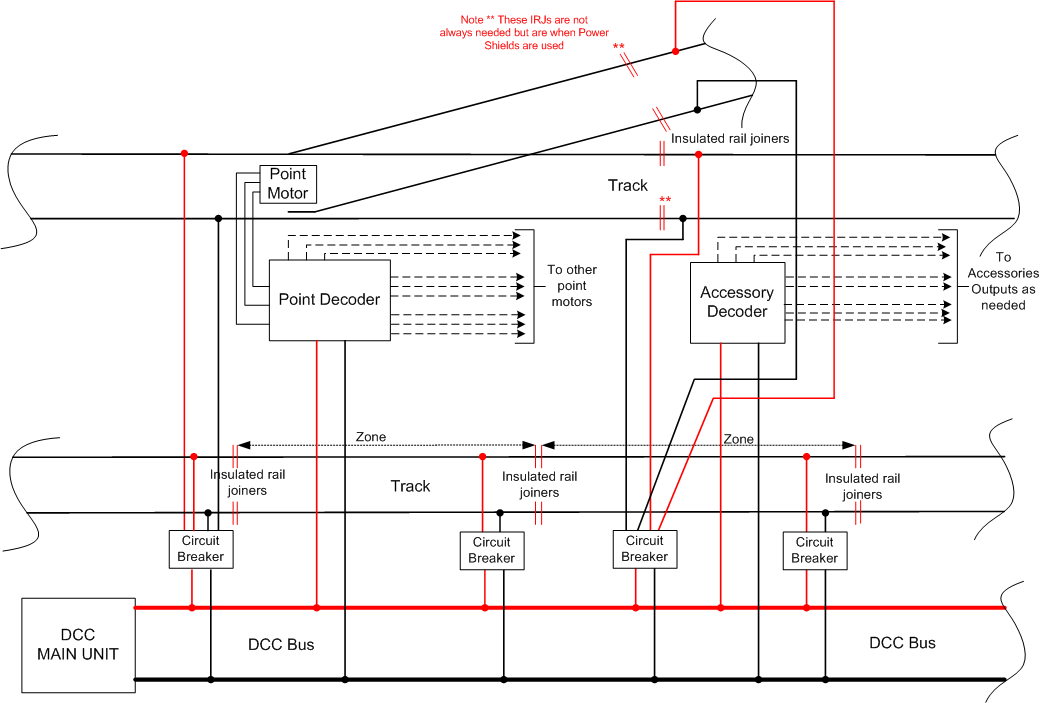
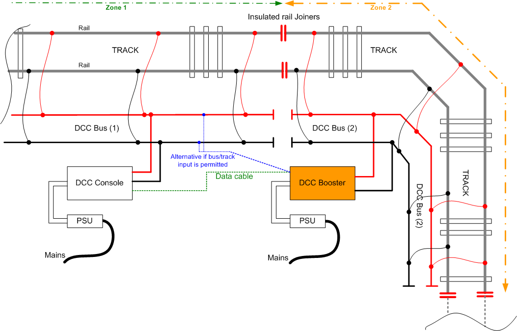
In the drawing below the complete DCC system of train control is shown. Track feeds, point and accessory feeds all derived from the main DCC Bus. Note: Circuit Breakers have been shown in all track feeds but these aren't absolutely necessary, but they do offer improved fault protection and localise any short circuit to just one section of track rather than the whole system shutting down. One circuit breaker is shown as a dual and separately protected output while the other three are single outputs (One has two feeds coming from the same output).
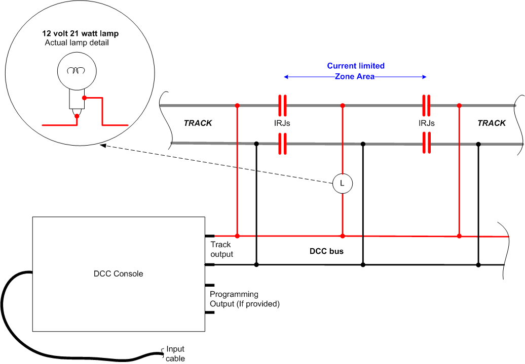
If the cost of buying several electronic resettable overload trips comes too hard on the budget, then perhaps consider the much cheaper and more simpler option of using car lamps to limit the current flow where a short circuit may occur.
Note; that the use of filament lamps acting as a current limiter, does not replace the main consoles main cut-out device or any other such electronic devises that may be installed around the layout. It simply limits the current being drawn from the console when a short circuit occurs.
You can wire typically a car *1156 style 12 volt 21 watt* reversing lamp (Or indicator lamp) between the DCC bus and one rail of an insulated section of track (Zone). If you have a very basic layout and a simple fairly low powered DCC console then wire the lamp into one feed lead from the console to the track.
* Note the actual wattage of the lamp needs to be below that of the rated current of the main consoles current output. This may mean on smaller low current DCC units using a 12 volt 7watt or 10watt lamp. Where larger currents are available and the needed to feed sections arises, then consider increasing the wattage of the current limiting lamp above 21watts. Example of current flow assuming 14 volts is the average track voltage. A 21watt lamp will pass approx 1.5Amp. 7watt lamp approx. 0.5A and 10watt lamp approx. 0.715 The sum being lamps rated wattage divided by the rail volts. E.g. 10watts / 14 volts - 10/14 = 0.714.
The most simplest overall current limiting device is shown here.. This wiring is only shown as a very simplified drawing to aid understanding of how the lamp is wired into circuit.
DCC Circuit over current protection.
There are several ways of preventing short circuits from doing serious damage to the control system.
The usual method is that the main DCC control unit has its own built in circuit breaker, which in some units are fully self resetting once the problem of the short circuit has been removed. While this will proved overall protection if it is tripped the whole layout stops. Which isn’t always ideal!
There are available ‘zonal’ short circuit protection devices which the DCC bus is fed into and then the output/s are taken to the track via local bus’s. These units are available in one, two or four individually operated zones on the same printed circuit board.
One of the suppliers is ‘Tony’s Trains’ in the USA, they can supply the Power Shield ™ devices at competitive prices. These are now being to becoming available in the UK and produced by other manufactures too. They are sold in the UK for example through such suppliers as 'DCC Supplies' or ‘Coastal DCC’.
These zonal protection devices are very fast to operate and in most cases will trip long before the main DCC control unit has registered a fault current flowing. They can also proved LED indication that they have operated making fault finding that much easier and faster.
Below is show the very basic zonal protection idea…
DCC Reversing Loops.
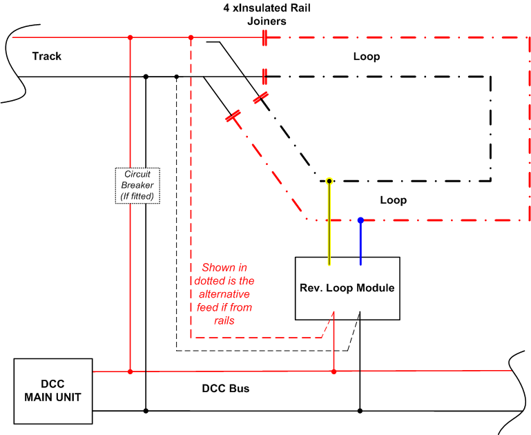
A reversing loop on a DCC operated layout normally requires the fitting of a special automatic Reverse Loop Module (RLM) **(see below). The problem, like all reverse loops, is the the top rail that is going into the loop meets the bottom rail upon leaving the loop - result would be a full short circuit occurring all the time. RLM modules often have four wires pre attached by the manufacture or four terminals for you to wire onto. They are wired with two wires to the DCC bus or the loops approach tracks rails and the other two directly to the rails of the loop. I would recommend always obtaining an all electronic RLM rather than the relay operated versions as they are much faster in operating which is an important feature to have. The loop must be totally insulated from the rest of the layout by the insertion of four insulated rail joiners at the entrance and exit of the loop
The length of the loop between the four IRJs should be at least the length of the longest train ever likely to run around the loop and ideally longer where space permits.
Principle of the auto Reverse Loop Module's operation.. A train approaches along the main line and enters the loop via the point and goes around the loop top to bottom direction. It can of course pass the other way around if chosen. For this example we'll assume the loops rails at the top are at the same polarity as the entrance tracks. The train passes over the top IRJs and proceeds correctly around the loop. While the train is inside the loop the point can be moved over. When the trains first metal wheels reach the exit (bottom) insulated rail joiners they cause a short circuit as the IRJs are bridged by the wheels and a positive rail is connected to a negative rail by the metal wheel. The result is an electrical short circuit, normally the main console would detect this short circuit and shut the system down until the short is removed. But the RLM detects the short occurring and flips the loops track power over in micro seconds and before the main console normally detects the short. The train continues on its journey as though nothing has occurred! The RLM remains in the last set position all the while the power is being supplied to the layout. So now the top pair of loop rails at the IRJs are at opposing polarity to the rails coming in from the point. When the next train passes into the loop, with the point reset to straight running, it crosses over the top IRJs and the RLM once again detects the short and flips the rail polarity of the loop the other way, allowing the train of continue around the loop uninterrupted and out onto the main line again once the point has been set correctly, as the loops bottom rails are at equal polarity either side of those IRJs So to recap, the RLM detects a short occurring and instantly flips its output over thereby allowing continued and uninterrupted running.
An RLM is wired as per the drawing below…
**Note; The reverse loop shown above can also, if wished, be operated by the point that leads into/out of the loop. By fitting ideally a double pole micro switch such as the Peco PL15 or alternatively using a DPDT relay operated via a single point micro switch, such as the Peco PL13. The loops feeds are then swapped over by the actual point moving over from one side to the other while the whole train is travelling around the loop. This then removes the need for the RLM module. This can be seen wired on the Electrical Pages under 'Reversing Loops'.
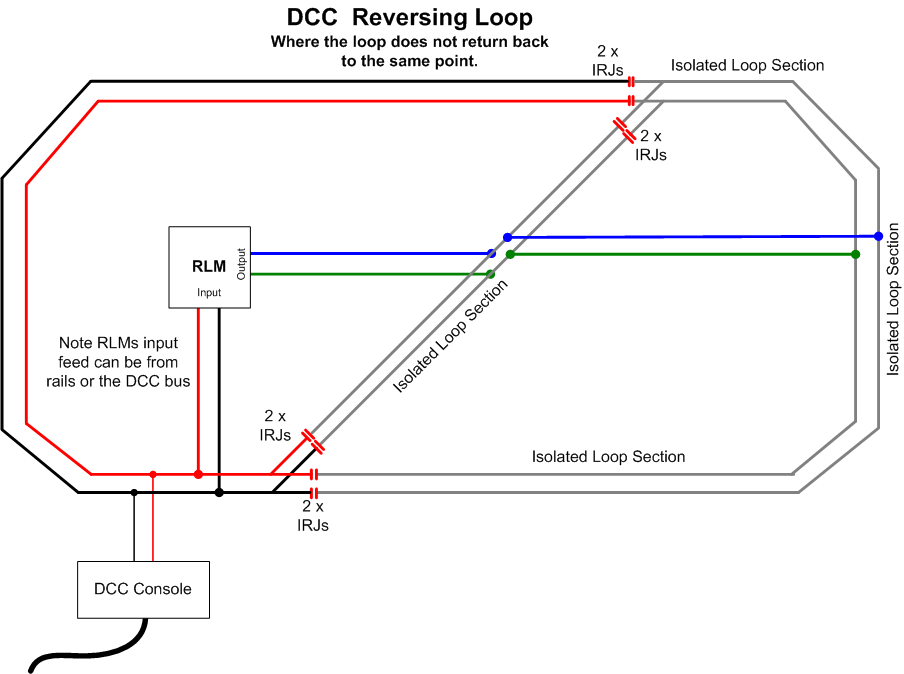
Where a reverse loop does not return back to its input point, but instead it cuts across the layout diagonally and uses two separate points, then the RLM is wired as shown below. Note the eight sets of insulated rail joiners used. Technically when using insulated frog points the two IRJs used at the top of cross-over diagonal track section aren't needed but are fitted for good practice.
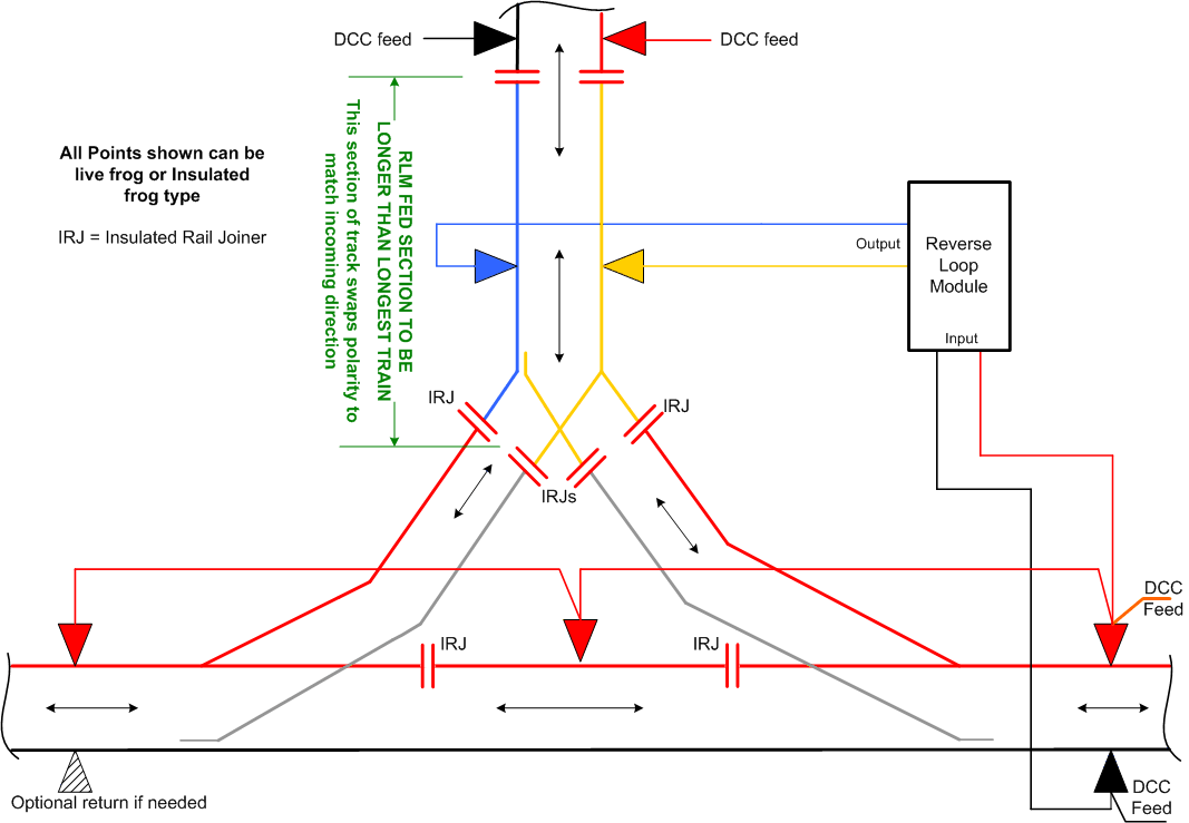
A Reverse Loop is also formed where a Wye (Y) track configuration is used. Here the easiest way is to feed the single line or tail end of the Y track from a Reverse Loop Module and then install a pair of IRJs at least the longest trains length away from the Y IRJs.
The drawing below shows the basic idea.
Notes: 1) Where Insulated frog points are used the two IRJs shown in the straight through track at the bottom are not needed.
2) If the top track is a dead end siding etc the two IRJs and the two rail feeds from the main DCC console are not needed.
Block Sections on DCC are possible with the aid of a suitable block detector unit. These are often produced in either the Diode or the current detection method. The current monitoring style being probably the less likely to cause any issues or interference with the DCC signal flowing to the rails. As all that happens is the DCC rail feed for that section of track is passed via a current detection device which is often little more than a small loop of wire around a ferrite core with a second coil feeding an electronic detection circuit which eventually provides a suitable output for feeding indications like LEDs, relays or other electronic devices etc.
A basic idea of block detection is shown below where two sections only are shown. Of course in reality there are likely to be more than two sections. The sections length will normally depend on the maximum train length plus some overlap margin too.
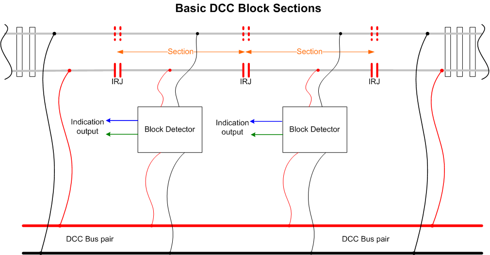
While the above is a very simplistic drawing showing the basic idea, reference to the chosen block detector units manual should always be made, as some units will require IRJs in the non detected rail (as shown by the hashed IRJ lines) while some may have the black feed wire running from the DCC bus directly to the rails and not via the detector unit itself.
BRAKE on DC.
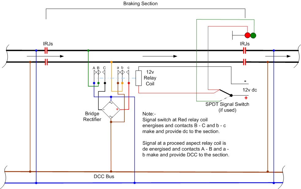
Some loco decoders offer a 'Brake on dc' option. To enable this, the dc operation on the decoder is disabled and the rate of acceleration and declaration of the loco is fine tuned via CVs 3 and 4 to give the locos a suitable slow down and slow pull away sequence (deceleration and acceleration). In the very simplest form as shown below, a signal is placed at the far end of the slow down section. All the while the signal is showing a proceed aspect DCC track power is applied to the braking sections rails and trains travel over the section normally.
When the signal is replaced to red the double pole change-over relays coil becomes energised (operates) and the contacts of the relay swap over, a full wave bridge rectifier is being fed from the DCC bus (or from the approach side rails if a bus isn't used) and now provides dc power to the braking section. As the loco enters the now dc fed section, its decoder senses the loss of the DCC signal and applies the pre set deceleration sequence and slowly brings the loco to a complete stop. The distance travelled from normal speed to stop is set by the decoders CV4 setting for that loco. Once the signal is cleared to a proceed aspect the relay coil is released (de-energised) and normal DCC power is applied to the section. The locos decoder sees the return of the DCC signal and slowly accelerates away to its previously set maximum speed . The acceleration rate will depend on the setting of CV3. Loco lights will normally remain on even when stopped in the section.
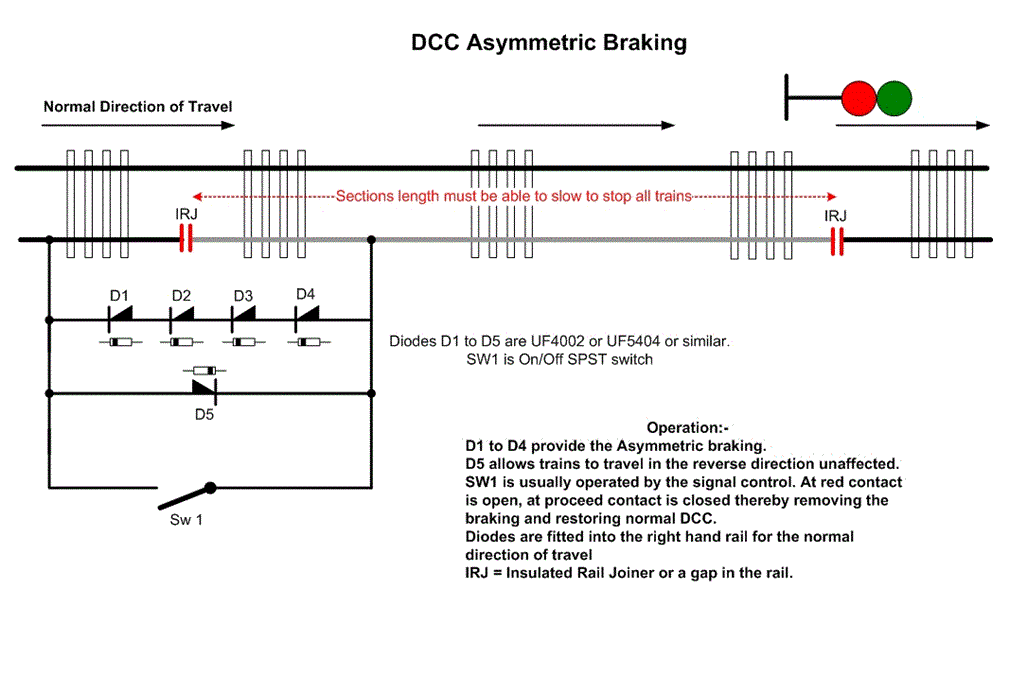
The other and possibly more popular method of slowing and stopping a loco and then allowing it to pull away again under its decoders defined acceleration rate, is to use Asymmetric Braking usually referred to as ABC braking. Here an ABC enabled decoder has to be used along with the basic slowing method of five diodes and often an override switch so a train/loco can pass through the section without stopping. Only one rail needs to be isolated and feed form the diode block as it is this altering of that one rails DCC wave from normal. The section needs to be sufficiently long to allow the loco to slow to a halt and all its pick up wheels need to be inside the section too. So its quite improtant where multi wheel pick up locos are used, such as EMUs or DMUS etc. Below shows the basic diode configuration.
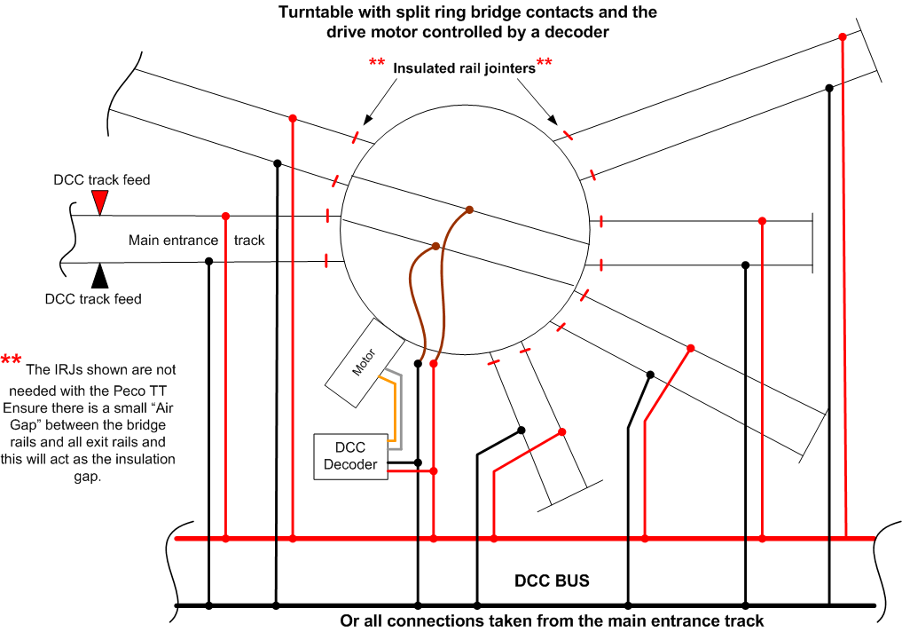
DCC & Turntables.
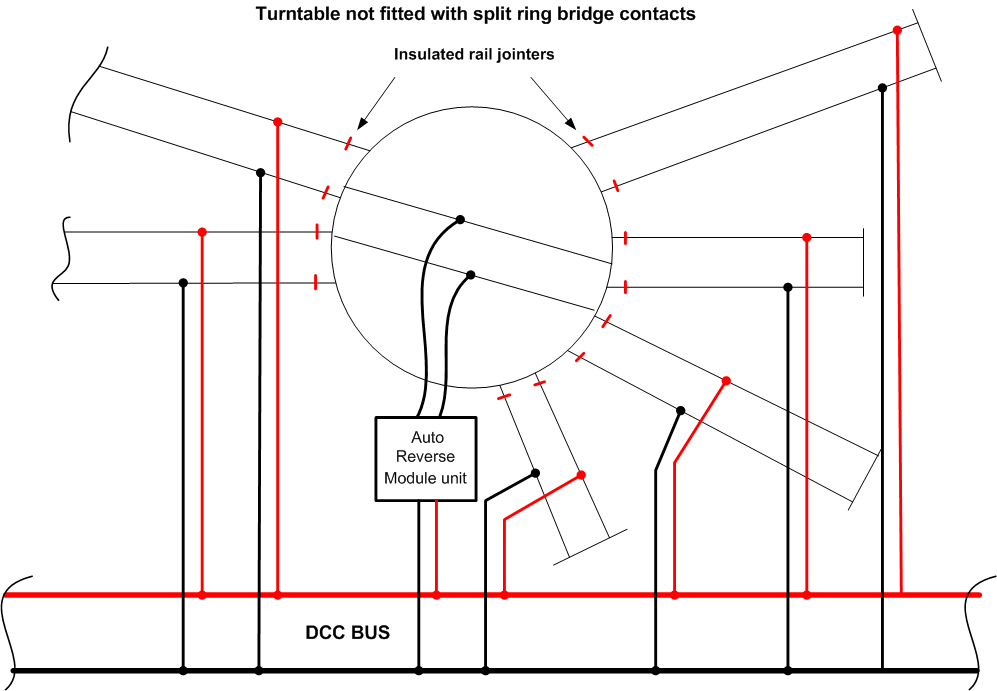
Often a turntable’s exit track is the only track to be livened up by the tables bridge being aligning with that track However with DCC we can have loco’s stabled on any of the exit tracks and their lights, sounds or smoke units still functioning or perhaps some minor shunting occurring etc. So there is a need to provide DCC power to all tracks exiting the TT. Also some styles of turntable can cause problems when a loco leaves or enters the turntables bridge, as a short circuit can occur due to the turntables bridge rotating through 1800 degrees and its rails being at opposite polarity to the entrance tracks.. Note: Turntables which use a split ring to feed the bridge rails normally don't require any adaption to the bridges feed or the installation of an Auto Reverse Module.
The exit or other storage tracks leading from the turntable are often pre wired to the turntable bridge track by the TT's manufacturer. If this is the case, insulate both rails on all approaching tracks just after the turntable and feed the rails on the turntables bridge from a reversing module or directly from the DCC bus if its of the split ring type (see lower drawing) . The approach and all other storage tracks are then wired directly to the DCC Bus or the main approach track for their track power.
Split ring turntable make DCC wiring that much easier. In the five drawings below and the final little video that links all the drawing into animated movement it can be see how easy a split ring turntable is to use.
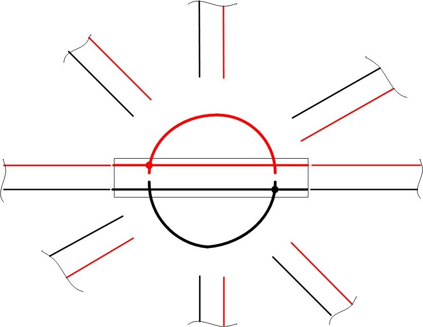
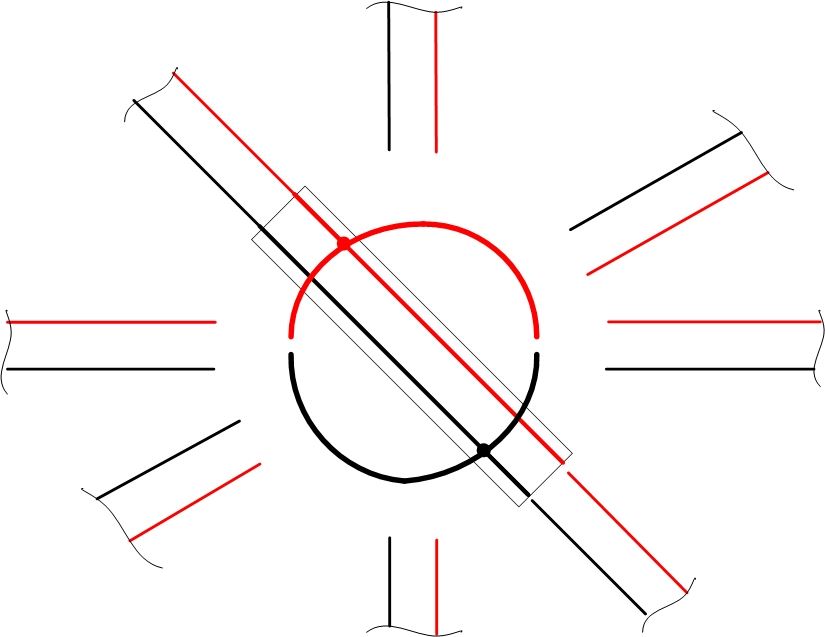
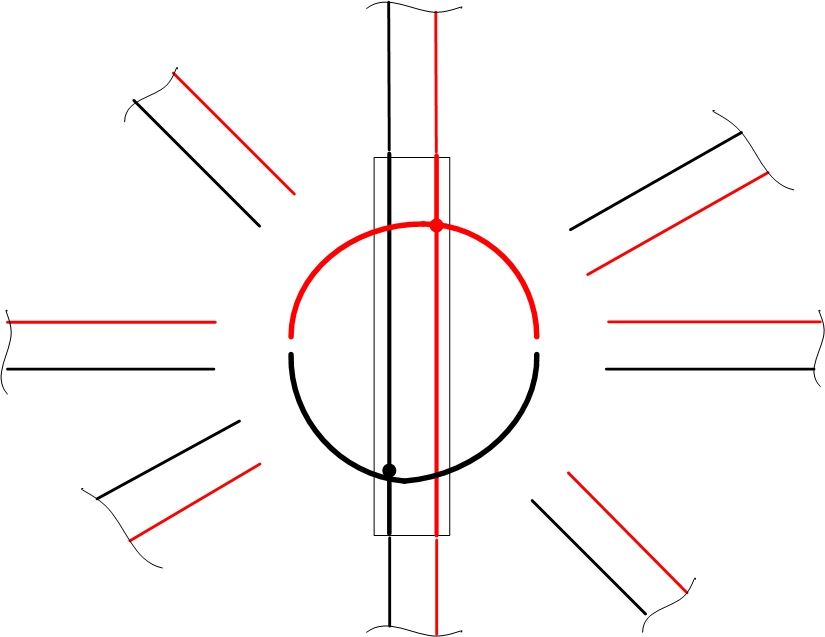
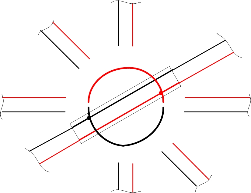
Below is a video of how the TT rotates and keeps the rail polarity correct
In the drawing below a typical motorised Peco turntable is being operated on DCC and it also has the motor powered via a decoder.
Note; that the decoders output is only connected to the drive motor and its input is from the DCC supply. If your TT is not to have the drive motor DCC operated then omit the decoder and its wiring. The rotating bridge rails are fed via the split ring underneath the bridge section and are powered directly from the DCC bus or from wires taken from the main entrance track. The use of insulated rail joiners is not necessary with the Peco TT, but there must be a small air gap left when each exit track rails are aligned to the TT bridge rails. This air gap acting as the IRJ. For non Peco TTs and where the manufactures have installed a small section of track fitted around the perimeter or alternatively there are electrical contacts on the perimeter which the track is laid onto by the layout owner and the exit tracks are then power by the TT bridge aligning to that track, then IRJs as shown will be need just after the TT on all tracks leading off of the TT.
Connect together all of the tracks to the bus or main feed track as shown, this then allows all tracks to be constantly live and provide full DCC functionality e.g. Loco lights or sound etc can be left on or shunting etc can be carried out on the longer tracks after the TT, even when the bridge section is not aligned with those tracks.
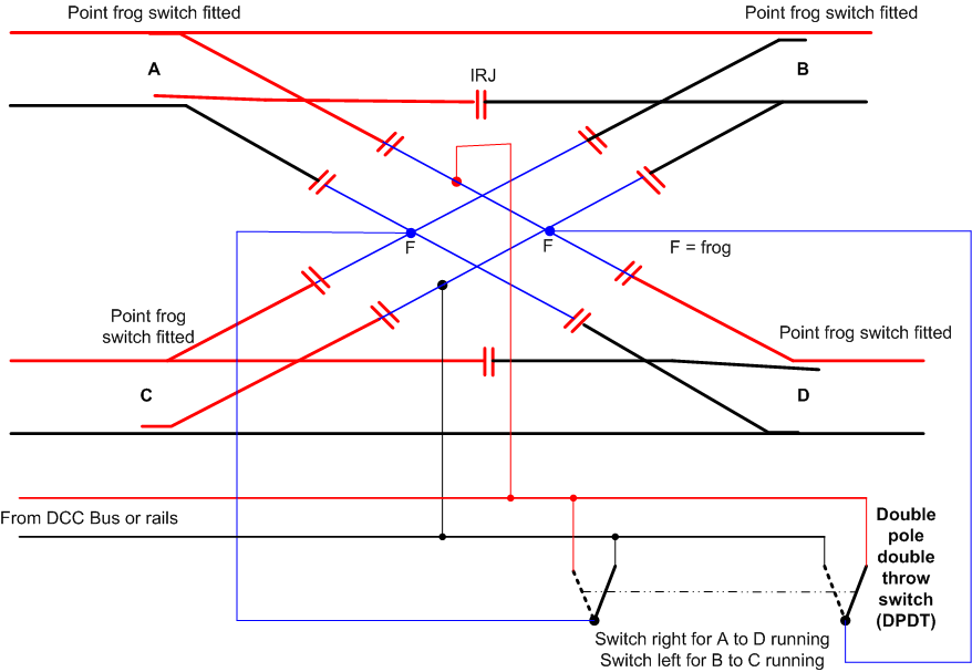
Electrofrog Diamond Crossing on DCC employs the use of a double pole double throw (DPDT) toggle switch to select the power feeds to the crossings live frogs.
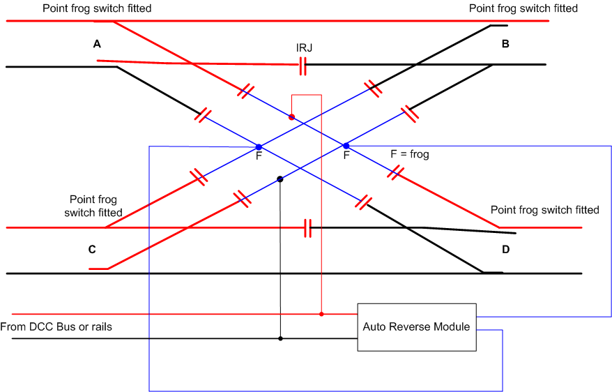
In the drawing below the DPDT switch shown above has been replaced by an Auto Reverse Loop Module to automatically switch the diamond crossings frog rails to the correct polarity as a loco passes over. I would recommend always obtaining an all electronic RLM rather than the relay operated versions. An alternative is the Tam Valley Frog Juicer here a Dual Juicer is needed.
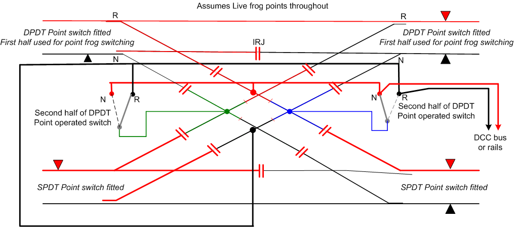
In the final DCC wiring for an Electrofrog diamond crossing the diamond crossings frogs can be switched via two point operated change-over switches such as Peco PL13 or PL15 twin micro switch is used where the actual points frog is also switched by the other set of contacts on the switch. Note only two upper sets of points control the diamonds frog polarity. The two lower diagonal points switch their direction in unison with the appropriate upper diagonal point. e.g. routes available = upper left to lower right or upper right to lower left or all set for straight running. It is not permissible to have all points set reverse together. Only one diagonal pair must be Reversed while the opposite diagonal pair are at Normal.
DCC Lighting.
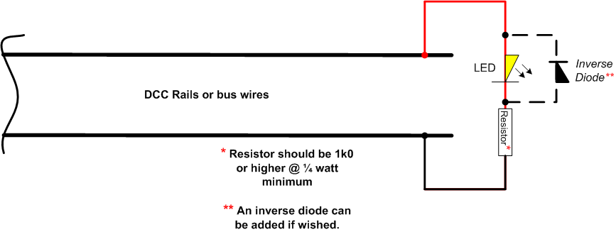
DCC power can be used for illuminating LEDs. In its most basic form this can be to light say a buffer stop lamp. The LED is connected across the DCC supply or DCC powered rails and a suitable series resistor is wired into the circuit. As DCC is a sort of ac style of power then there is an option of adding an inverse parallel diode across the LED to protect the LED from reverse polarity voltages. This diode can be a 1N4001 or smaller 1N4148 I do not recommend wiring filament lamps on a DCC supply as their current demand is far greater than LEDs. Equally I wouldn't wire too many LEDs on the DCC bus or rails either. Though their current demand is much lower. If a larger amount of illumination is required consider obtaining a regulated 12 volt dc power supply and feeding all illumination from that. Note; you can not add an inverse diode to an LED that has a built in resistor, such as those rated at 12 volts etc.
Below is an example of am LED and its series resistor wired across a DCC powered bus wire or rails.
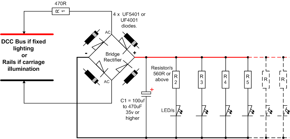
The DCC power can be used to illuminate LED carriage lights without the use of decoders. For a pound or so (GB£), some very basic electronic items can be obtained and soldered together to make a suitable circuit to illuminate carriage lighting via a set of metal wheels on insulated axles and a pair of wiping contacts etc. In the circuit below the DCC power is taken into a bridge rectifier. This can be made up by using four individual diodes, such as the UF4001 or UF5401 diodes. From the DC output of the rectifier the power is then passed along to the individual LED/s via their series resistors. The resistors R2-5 etc can be 560R to 1K0 or higher OHMs and each LED has one resistor in its positive (Anode) feed leg or they can equally be wired into all the Cathode sides of the LEDs. You can connect as few or as many LEDs as needed onto the outputs. So long as the maximum output of the rectifier isn't exceeded. Note the electrolytic capacitor fitted across the output from the rectifier gives some smoothing to the circuit and in the case of carriage lighting a very small amount of power when the coaches wheels may not be fully in contact with both rails (Passing over insulated frogs etc) to help reduce flicker. The resistor R1 is added to help prevent the DCC seeing an overload when the DCC power is initially turned on due to the effect of the capacitor charging (Inrush current).
Turning off the lights if required can be via a simple On/Off slide or toggle switch inserted into one of the DCC supply wires going to the rectifier.
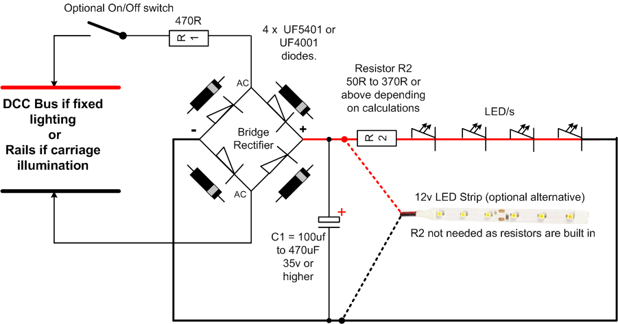
In the drawing below a similar arrangement of LEDs is used but this time each LED is wired in Series (daisy chained) to the next LED. Only one resistor is used for the whole chain of LEDs. The actual resistor value needs to be calculated, but will be (depending on the number of LEDs) in the region of 150R to 370R. There is today the option to use a LED 12 volt strip instead of the induvial LEDs. The electrolytic capacitor is used to help overcome the flickering effect where pick up wheels fail to make good contact continually. The actual value will depend on the physical space available, but ideally needs to be around 100µF to 470µF at ideally at 35 volt rating. If using a 12 volt self adhesive LED strip then the series resistor R2 is not needed as these strips have built in series resistors.
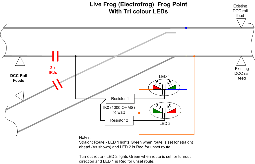
Point Indications using DCC. It is possible on DCC layouts to use the DCC feed to power indication LEDs on the Mimic Panel. While I recommend whenever possible using a separate power supply for indications, as per those shown on the Electrical pages, it is perfectly possible to use the DCC rail power. So long as your DCC power supply is of a suitable current rating to power both the locos and the LEDs, which most will be. Note; on average each lit LED will draw between 0.008 and 0.01 milliamps (8 to 10 milliamps). So even 20 LEDs lit at once would only equal 160ma to 200ma.
You can install LED indication to both types of points - Electrofrog and Insulated frog. But with Insulated frog points it will be necessary to fit two Insulated Rail Joiners (IRJs) to the ends of the points Vee rails and then add new DCC rail feds after the IRJs. Electrofrog point users will normally have these IRJs fitted as standard.
The drawings below show the two types of points and how the LEDs can be wired to them.

On Electrofrog points the LED wire to the points frog can be wired to the switch contact on the point motor that feeds the frog rather than directly to the frog as shown. e.g. Seep PM 'F' contact or the off set contact on a Peco PL13 etc.
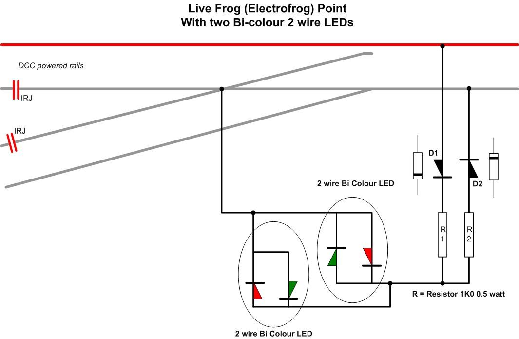
The three drawings below shows two separate LEDs The first using single LEDs and the following two Bi and Tri coloured LEDs - 2 lead and 3 lead common Cathode type.
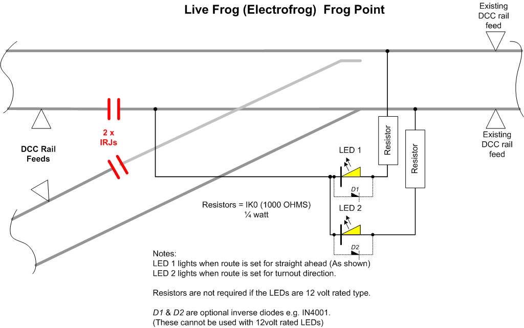
Using Bi or Tri-colour LEDs each LED can be lit to show red or green indication. Green being for the route set while the red is for the unset routes direction.
All items appearing on this or any page of this web site are the intellectual property and © copyright of Brian Lambert. Unless otherwise stated.
You MUST NOT make available by placing them in any public domain area or in printed format any copies of Text, Image, Drawing or Video shown on this web site.
No item as listed above should be used, copied, linked to or forwarded by any third party without firstly obtaining the written permission of the web site owner - Brian Lambert.
You may freely and for personal use only, copy or print any areas.
You may refer to this web sites page electronic address detail (URL) in any other media - printed or electronic. Any such referenced URL should commence.... https://www.brian-lambert.co.uk/
Brian Lambert accepts no responsibility for any item appearing on this or any other page of this web site.
All items are given in good faith.
By visiting this web site you agree to accept and abide by all the condition shown above.