www.brian-lambert.co.uk

Here I will help with wiring a layout
Firstly a word of warning.... Never, ever allow mains power (230v AC in the UK) to go onto the railways baseboard's. If 230 volts is allowed onto the baseboard there is a very serious risk of electrocution and possible death. Only safe extra low voltage should be here. Mains supplies and all the associated transformers should be housed in commercially made or expertly produced safety enclosure. These should either be 'floor' or 'off layout' mounted. Umbilical multicore cables or individual wires then supply the low voltage power supplies onto the layout.
The only exception to this rule is where a controller has a mains input supply requirement and then the mains power is fed to the controller via a flexible mains cable and at times via a special three pin "Kettle" or "Computer" type mains plug and socket in the casing of the controller. e.g. The Hornby HM2000 has such a requirement. The mains cable and all its connectors that feed the controller should be regularly inspected for any signs of damage and any noted should render that supply cable or controller unit unusable until it is replaced or professionally repaired.
Now perhaps is the time to start thinking of how the final layout will operate. Will there be just one operator or more? One or more mimic control panels or basic controller locations. Assuming for all these discussions from here on, just one control point has been decided upon and provision for at least two operators provided, though one person can operate the layout single-handedly, if need be. Draw out your track plan and then start to consider where track power feeds will be required and where any Isolating sections will need to be installed. Remember on dc layouts always feed the track power into a set of points from the tip or switch blade end, NEVER back feed from the frog direction. When using Live Frog (Electrofrog) points you should install two rail isolating breaks, one in each rail after the frog ideally at the two Vee rail ends leading away from the frog. Where a pair of Electrofrog point make up a cross-over both rails where the two points abut each other will have insulated rail joiners fitted. Don't forget when using live frog (Electrofrog) points on a passing loop etc you should always insert an insulated rail break at both ends of the loop ideally at the ends of the Vee rails from the points, as this prevents any electrical short circuit problems occurring. If you're using Insulated frog (Insulfrog) points such as Hornby, Peco Setrack or their Streamline Insulfrog "SL" versions then the use of Insulated joiners is all but removed, expect for isolating track sections. On these type of points the frog and point blades switch the rail power and they are self isolating, providing track power only to the direction the point is set to. But the dc electrical feed must flow into the point tip first, is still a necessity. See the section below on Points for more details.
The Beginnings.... Many will come into the hobby with a basic train set layout. Often an oval of pre curved track and a few straight sections making up the basic layout. Inside the train set's box will normally be a plug-in mains adaptor to safely reduce the mains supply to around 12 to 16 volts. A controller to enable the operator to control the speed and direction of the train, a locomotive, coaches and/or wagons and the track, plus quite often a power connecting clip or a special length of straight track that has the tracks power connection built in. While this simple system will proved the basics and give enjoyment for many hours, there is often the need to improve over and above that of the basic train set. So the beginner returns to the model shop and purchases more track to make another loop and perhaps a point or two. They assemble the new outer loop and connect the two tracks together via a new cross-over set of points, then wonder why the inner or outer loop doesn't work or occasionally stops for some reason.
The main reason is that a second controller is required for the new loop. So from the basic train set set-up we now progressed to having a twin tracked railway controlled by two independent controllers. Sidings are then added and perhaps a third loop or even a high level section with track passing over one or more of the lower lines and eventually rejoining the main loop elsewhere. All really good fun and what a wonderful way to enjoy oneself and perhaps enrol the family members too.
But the need to control the layout further and in more detail is now required. The builder probably wants to be able to stop one loco in the platform and then shunt the trucks or coaches off into a siding by using another loco. Perhaps in another siding there is a twin tracked loco shed and it would be good to be able to run several locos into the shed, storing them one behind the other without the first one moving. But this siding is fed from the main line by a set of points which are right at the back of the layout, so electric point control is needed too. We now need several isolating track sections and a few electrically operated point motors. These options are quite straight forward and on a dc controlled layout you will have to start wiring and installing insulated track sections (Isolating sections) and wiring specially switched feeds to them and even install your chosen type of electric point motor and the means of switching the power to them.
So, the above is very simplistic and perhaps not how your layout has come to be. But the basic idea is the same, in that at some time in the overall hobby of model railways you will have to carry out at least some basic electrical wiring. So don't be put off. Not knowing an amp from a volt or ac from dc isn't a means of preventing any further work. Hopefully the following items should help you understand how all this comes together and how the layout works.
Electrical Basics.... Our model railway is powered at a safe nominal 12 volts direct current (dc), the exception being DCC layouts which use around 14 to 16 v ac and even this isn't a true form of ac! The 12 volt dc can come from a couple of sources, such as a battery (car batteries and dry cells were used many years ago) or more commonly now from a mains to safe extra low voltage 'plug into the wall socket' power pack or perhaps a via a directly fed mains powered single, twin or more knob controller. So, each 'controller' allows for totally separate operation of a section of railway track via its control knob or slider. The more you turn up the controllers knob more of the nominal 12volts is provided to the rails. e.g. from 0 volts slowly up to maximum volts of around 12v. Note; the actual full voltage supplied may be higher than the nominal 12volts. Some basic controllers can exceed 20v dc when turned on and no locos are on the rails - i.e. No load voltage. It is conventional to have the right-hand rail, when looking along the loco towards the front, at a positive potential to obtain forward travel. As previously stated, some controllers have one knob thereby powering only one track, while others can have up to four controller knobs allowing four separate tracks to be fed and independently controlled from each other. The output to the track from the controller is called the 'Controlled' output. In addition some makes of mains powered controllers also offer other outputs which are not controlled by a knob or slider, such as a 16 volt alternating current (ac) output and / or a 12 volt dc output. These are both called 'Uncontrolled' outputs.
These additional outputs are used to supply power to other functions. The 16v ac supply is normally used to power point motors (Solenoids) via special switches. While the 12v dc being quite often used to supply such items as building internal illumination, street or platform lighting, powering turntable motors or even feeding another slave and non mains powered controller. More of all this detail later...
Below is shown the basic means of connecting the output of the train controller to the rails. Two wires run from the controlled output terminals on the controller to the rails. To make the rail end connection as easy as practicable, the manufactures of the track produce 'power clips' which can be simply pushed into the gaps under the rails and between the sleeper spacing webbing. The top of the connector touching the underside of the appropriate rail allowing a very easy push fit electrical connection to be made. The stripped of the wire simply plugs into the receptacle in the end of the clip. The alternative to the 'plug in' power clip is the powered track section. This is normally a short length of straight fixed section track with built in power connecting terminals. All three styles are shown below.


Of course there is another way of connecting the track power feed wires to the rails, and that is by soldering the wires directly to the outer web of the rails or to the undersides of the rails if the track has still to be laid in position. See the examples under the heading Track feeds further below.
On dc powered layouts the standard is that when the right-hand rail is positive and looking along a loco from the cab end towards the front or chimney end on steam outline locos the loco will move forwards.
This simple drawing shows the idea.….
In the two very simplistic drawings below it can be seen how the basic train set increases from a single tracked loop to a twin looped layout and a second controller. If you wish to make the loco travel in the opposite direction use the controllers Reversing switch or swap around the two wires at the controller end connection or at the rail connection end, but not both!
Below is the same two loops of track as shown in the previous drawing but now with a cross-over point added. Note the use of a pair of Insulated Rail Joiners (IRJs) to electrically separate the two loops / controllers. To pass track to track both controllers are set to the same direction of travel and roughly the same speed. The loco travels from one controller to the other as it passes over the cross-over and the IRJs. Then the first controller can be turned off and once the train is clear of the cross-over points the points can be put back to their Normal straight ahead position.
NOTE *: Older locos where pick up is from the front wheels on one side and return is via the rear wheels on the opposite side the two Black feed wires should be linked or the IRJ shown on the left can be removed and replaced by a metal joiner. However, this can only be carried out where the two controllers are fed from totally separate power sources or from a twin wound transformer. Dual controllers should be specified as 'Suitable for Common return wiring'.
Always try to arrange track power to flow into a point from the points single (Tip) end then its switched by the actual points position. This simple example shows a section of a twin tracked railway with two controllers each feeding their own tracks. Note the two Insulated rail joiners (IRJs) replacing the metal joiners in the cross-over rails these keep Track 1 controller electrically separate from Track 2 controller. See Note * above
Now the layout has a second cross-over pair of points and a siding added, plus a switch to isolate the end of the siding. Adding far more operating interest. As an aid to help me depict the tracks in a drawing, they are now shown as being in different colours or just one or two colours.
Isolating Sections... On the railway there will probably be a need for sections of track that can be separately isolated, to allow the storage (stabling) of locos while the rest of the railway can be operated normally. This is done by inserting an Insulated Rail Joint (IRJ) in one rail. Then the track beyond the IRJ is fed via a simple On/Off switch. By turning the switch Off the section beyond the IRJ is isolated or cut off from the track power, when the switch is On (Switch contact closed) then that track section is powered as normal.
In the above drawing an insulated rail joiner (IRJ) has been used in one rail of the siding to enable electrical isolation from the rest of the siding and any other track areas. The On/Off or Isolating switch provides track power as and when required to the Isolating section of track beyond the insulated joint towards the buffer stops. When using Insulated frog points the whole siding will only be live electrically when the sidings entrance point is moved over to the route leading into the siding and the end isolated sections on/off switch is turned on. An alternative is to take the sections feed directly from the controllers terminal that also connects to the same handed rail elsewhere and this is shown in the simple layout design below. Any number of IRJs and associated switches can be used and two or three sections of a siding or main line (in a station platform areas for example) can be switched on /off as required by their respective isolating switches, thereby giving much more controllability to the railway.
A simple example below shows three isolating sections wired back to the main controller. Then each section is switched 'On' as needed to allow a loco to proceed from the main line towards the buffer stops on the right. Each 'Section' has to be longer than the longest loco to be held. The proceeding loco can be held electrically isolated in any section. and another loco run into a clear preceding section if wished. Three isolated sections are shown in the example, but there could be just one section or many more than the three shown, depending on the length of the track.
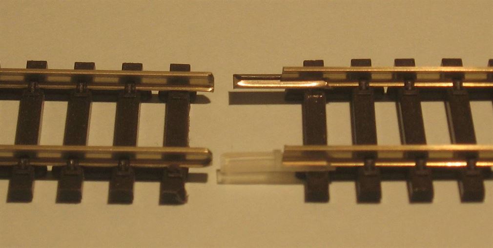
The picture below shows a Peco insulted rail joiner (nearest rail) and a metal rail joiner. Note the insulated joiner is manufactured from a Nylon type material and has a small end stop or end post to prevent the two rails touching end to end.
So, now in our simple track design we can add another isolating section of track, possibly in a station area. Only one such section has been shown below for clarity, but many sections can be included. Each controlled by an On/Off switch and fed from the appropriate controllers output. Note on a loop of track two IRJs are need - one at the start of the isolating section and one at the far end of the section.
Where a fan of sidings independent of the main line two controllers are used and a selection switch allows the operator to select which controller powers the sidings. This then allows shunting within the sidings area with the main line entrance point set against the siding and the main line running separately. Also it may be very desirable to hold locos at the ends of sidings while still being able to operate the rest of the sidings. In the very simple two drawings below the track layout is shown in the upper drawing with the isolated joiners fitted. Note the pair of joiners needed at the siding entrance from the main line and the two electrical track feeds and three isolating section feeds at the sidings ends.
In the lower drawing the actual wiring needed to accomplish this is shown. One Single Pole Double Throw (SPDT) toggle switch is used to select which controller is to power the sidings or it can be a Hornby R046 yellow lever, but this would not provide centre off. Three isolating switches provide track power selection to the siding end portions. These are Single Pole Single Throw (SPST) toggle switches they can be Hornby R047 green lever switches etc.
Note: that due to the Common Return wiring the two controllers must be fed from separate power supplies or transformer windings and the controllers outputs are linked on one output terminal as shown.
Auto Stop.. at a sidings end (DC layouts only). A useful item for dc operated layouts is the 'end of siding auto stop'. This is nothing more than the normal IRJ (insulated Rail Joiner) fitted into one rail at least the longest loco or multiple units overall length plus about 50mm back from the buffer stop, it can be longer if wished. Then a diode is connected across the IRJ. The loco is driven into the siding as normal and when all its pick-up wheels (those wheels that pick up electrical track power) are beyond the IRJ, the loco automatically stops as the diode is blocking the positive inward direction current flow. By reversing the controller and this automatically reverses rail polarity feeding, the loco can be driven out as normal. If wished, a non locking push to make style push button can be wired across the diode, so as when the loco enters the auto stop section pressing the push button allows the loco to run further into the section. Releasing the button will stop the loco once its beyond the IRJ. In the circuit below it is assumed that the lower (right-hand when facing forward) rail is at a positive polarity when the loco is being driven into the section. When rail polarity is reversed the upper rail become positive and the insulation gap is bridged by the diode allowing the negative current to flow through it, thereby allowing the loco to leave the section. If the loco doesn't automatically stop when all its wheels have passed over the IRJ then reverse the diode.
Wiring.. I cannot stress most importantly the usefulness of a wiring diagram book on any layout that has more than just a basic track configuration. Each wire and termination place is drawn and then easily found should at anytime in the future there be a fault or need to alter something. Make it simple to understand and above all show each wire as a simple single line on the diagram - See the example below.
Below can be seen the wiring diagram for a basic controller feeding one track or loop etc. It has several feeds taken directly to various sections of the track it controls to allow improved electrical performance around the track. In addition and taken off of the main feed is another wire that passes onto Isolating switches (On/Off switches) which improves the final operation of the railway by providing sections of track that can be switched off (isolated) and the remainder left powered. i.e. ends of sidings or in platforms where a loco may be held while another is running etc. The isolating sections should have plastic rail joiners fitted to one rail where the isolating section is at the end of a siding, or two joiners spaced a suitable distance apart to provide a section of rail that can be isolated, such as in a platform where the isolating sections length will be the longest locos length plus a but more spare for stopping distance inside the section.
When planning the layout always try to arrange for rail power to feed into a set of points at the tips and out via the frog end. This will ensure power is routed in the direction set by the point.
A simple example is shown below.
The very simple track plan below uses the above wiring and is a basic loop of track and using Insulfrog points it has three sidings and one platform loop. Note that at the top there is a complete break in both rails made by inserting two insulated rail joiners, this isn't always necessary but does prevent a back feed occurring into the siding point leading off the main line (Always feed into points never back from the frog end). Note that technically the second feed connection bottom right isn't strictly necessary if the top pair of IRJs are omitted, its only there to improve electrical conductivity. All sidings only have power to their rails when the point is switched to that siding. The isolating sections at the end of each siding, when turned off (Isolated), permit loco berthing and they allow another loco to enter the siding as far as the insulated rail break, but not actually passing over the IRJ or beyond it unless the appropriate isolating switch is turned on. One siding has two isolating sections and this allows two or more locos to be stabled. Both platform tracks have isolating sections which when isolated allow locos to be held in that section while the rest of the layout is operated normally. e.g. A second loco could remove the coaches or trucks from the isolated loco and take them into the siding or the other platform etc.
Below I have shown the same track plan, but this time the layout is using live frog (Electrofrog) points, so additional insulated rail joiners (IRJs) and track feeds and returns are needed. Do not be alarmed by the two types of points used in model railways - Insulated or live frog, these are described in much more detail later on in the Points section.
Track Plan.. Draw on to your track plan the power feeds as open (or coloured) triangular fillets for all the feeds and solid black shade triangles for returns. I usually give each feed a unique sequential reference number. Draw in the isolating section feeds and give these a differing and unique reference number. e.g. Iso 1; Iso 2 etc. I advocate the main track feeds as being marked as 1xx, 2xx or 3xx etc. following on by the next sequential number. So you end up with all the feeds in one direction being 101, 102, 103 and the other line as being 201, 202, 203 etc. Any other feeds become 301, 302 etc. All this may seem a little unusual and strange, but it will become clear later on. See the extract below. Note this also shows several 'Sig Iso' sections with blue triangles, where the track at a particular signal is automatically isolated when that signal is at red, but powered when the signal is at a proceed aspect. All the points are numbered and the "N" denotes the side of the point blade that's closed for Normal running. Note the insulated rail joints are all shown too and in the drawing below live frog (Electrofrog) points are being used, hence the increased amount of insulated joiners needed.
Common Return.. Now we have a plan which shows all the feeds and returns. It’s time to decide on the type of wiring return arrangements to be used. I opt for a one wire Common Return system. This is where every return path is connected together and then one (or more if need be) return wire(s) go back to the controllers or power supplies output terminals for all supplies - ac and dc. The reason I choose this method is its simplicity of wiring and the reduced number of wires needed to get back to the controllers and power supplies. There are of course other methods of wiring and by no means is Common Return any better than any other. The other simple method is giving each return it own direct wire path – this is hugely wasteful on wiring. Another alternative is to consider splitting returns to say all Track power supplies, all Point power, all Signalling, all Lighting & everything else i.e. up to five return paths. I really can’t see any advantage in this over the conventional one wire common return system. Note; I do not recommend Common return wiring be used for DCC systems. Nor do I recommend common return be used where a mixture of DCC and analogue controls exist. e.g. DCC loco control and points fed via analogue should not share the same return wiring.
One thing that must be absolutely certain before common return can be used, is that each power supplies output comes from a totally separate winding on the transformer or has totally separate transformers. One transformers winding feeding two outputs will result in a certain short circuit occurring under the common return system.
In the above diagram it can be seen that all the return paths are joined together and ‘connection bus bars’ (Denoted by the solid dots) are arranged along the length of the layouts common return wires route to enable connections to be made from all the tracks, point motors, lighting etc returns. The Power Supply box shown above is only a representation and not meant as any particular power supply units which can be Single or Dual wound transformers, single plug-in to a wall socket sealed power units etc.
Wire itself… I prefer to use single flexible wire, nominally available in 7/0.2mm, 16/0.2mm, 24/02mm and 32/02mm the last two are often used for common return wiring – which I keep to a black coloured wire sheath. The numbers '7/0.2'mm mean for example:- 7 is number of strands inside the PVC sheath and 0.2mm is the actual size of each of these wires in millimetres. So there are seven copper wires each of 0.2mm² diameter inside the sheathing (16/0.2 has 16 individual wires inside it). The colour of the sheathing matters not, Red, Green, Blue, Yellow etc you can use all one colour or decide to make a specific colour for one function e.g. red for all track feeds and perhaps all point feeds in blue etc. it’s your choice. It may be a little less expensive to buy ten or more rolls of one colour wire than two or three rolls of differing colours.
7/0.2mm² can carry nominally 1.4 amps, so it is ideal for some model railway wiring in “N” & “00” gauges, but use it with caution, and keep wires running in this small size short in length, especially where any track feeds are concerned. Its larger brother, 16/0.2mm can carry at least 3.0amps and is suited to the larger gauges of railways (“0” or “NG” etc). 16/02mm is also ideal for “N” and “00” gauge solenoid point motor wiring between the operating point switch and the actual motor. Use 16/02mm on most point operation wire runs and use even larger sizes of wire on runs that exceed 21 feet (7m) e.g. 24/02mm. For the smaller layout 24/02mm will make a good choice for the common return wiring, where at any one time there might be three or so amps flowing, on larger layouts consider 32/02mm or even 50/02mm wire for the common return if need be. You can of course 'double up' the common return wires (e.g. 2 x 16/0.2 wires connected together will roughly equal one 32/0.2mm wire) as this will give more current flow potential and help overcome any volt drop problems.
I really don’t like the use of solid single strand wire, mostly this is the so called bell wire or ‘Post Office’ style wire (ex telephone wiring). While it will work, it does suffer from low current capability and volt drop problems due to its small conductor size and I find it breaks far too easily and is certainly not suitable for any layout that is portable. So keep with the flexible types!
Soldering.... There is only one way of making a solid electrical connection, as far as I’m concerned. That’s by soldering! People shy away from soldered connections and I can never really understand why? The basics are:- Soldering iron of suitable size for the work being undertaken with a clean bit, 60/40 Rosin cored solder and clean connections. I would not recommend the use of Lead Free solder which has its place, but doesn't flow so freely as 60/40 and also requires a higher soldering iron temperature, which many older irons can't quite reach.
Lets make a start…. For everyday soldering a 25 watt iron with a small to medium sized bit is all that’s required. Larger bits sizes and bigger wattage irons have their place, but not for most electrical joints. I use two irons in the main. An Antex 25 watt or an Antex 18 watt. Both do the identical jobs, it just that the smaller wattage one has a 1mm dia. tip fitted while the 25 watt one has a 2.5mm bit. The smaller bit is ideal for electronic printed circuit board work. If you can afford one then a temperature controlled soldering station of 50 to 60 watts is an ideal allrounder.
To make a good quality soldered joint, heat the iron for at least five minutes. Don’t rush, the irons tip must be up to full temperature. Have to hand a damp, soldering iron's tip cleaning sponge pad. If you own a soldering iron stand its likely it came with a sponge. If not, then cut a piece of ordinary sponge and use that. (I’ve used pieces of car wash sponge, but best of all is a cut up kitchen cleaning sponge!) Remember to keep the sponge damp. Once the irons hot, wipe the tip onto the sponge to remove all previous oxidisation and old solder residue. Assuming the tip is in a good condition, apply a little of the rosin cored solder to the tip. On electrical joints never use solid stick type solder or so called ‘tinmans’ or the paste and most liquid types of flux, as these all contain a mild acid which over a long period of time causes high resistance problems within the soldered joint. Solid solders and most liquid fluxes are normally the reserve of the solid sheet metal soldering jobs – Loco building, plumbing etc. There is one exception and that is the use of a special flux specially sold for electrical work -do ensure the flux is of that type. Examples are DCC Concepts Sapphire No-Clean Flux and flux sold under the 'Reflow' title ideal to use.
With the irons tip coated in liquid solder (wetted) and having previously dry assembled the joint (It must be cleaned too, use a fibre glass brush or scrape the surfaces of both components clean, unless its freshly stripped wire where the sheathing keeps the surface of the wire nice and clean) place the wetted irons tip directly onto the connection. Wait a few seconds for the heat of the tip to transfer into the components and then apply a little more rosin corded solder onto the heated joint, not onto the irons tip. You should see the solder start to melt and flow into and around the joint. Once sufficient solder has been applied to coat the whole joint, remove both the iron and corded solder. NOW DON’T TOUCH or MOVE the joint. Wait at least 10 – 15 seconds after removing the heat to allow the joint to cool and the solder to set. What you should end up with is a solid, clean joint. Sometimes the PVC sheath on the wire/s being soldered will shrink back a little. This is a nuisance at times and is due to a) The wires PVC sheathing having a low temperature range or b) Too much heat applied to the joint for too long a period.
I like using heat shrinkable tubing over any ‘In line’ joints, while it’s a lot more expensive than insulating tape, once shrunk down it gives a joint a more professional and secure finish.
Finally, before you go onto solder another joint or you have finally finished and before you disconnect the iron, clean the tip again on the damp sponge. You will get a many years of use from a soldering iron if you keep its tip clean!
Soldering wires to the bottom or outside of the rail is the same principle, but here I find pre tinning both the end of the wire and the pre cleaned place on the rail where the wire is to connect the best method. Pre clean the rail with the aid of a fibre pen or other means - fine Emery cloth, use a file etc. Tin with a little solder - tin both the place on the rail and the stripped wires end (Tin = coating the surface with fresh solder). Once tinned, I then place the wire end, which if necessary has been bent to an small L shape, up to the solder on the rail. Apply a little fresh solder to the irons tip and place the iron on top of the wire and lightly press down towards the rail. The hot solder on the irons tip will cause both the wires solder and the rails solder to melt into one. If necessary, apply a little more cored solder onto the wire with the iron still in place should there not be enough on the rail to make a solid connection. Carefully remove the iron and ensure the wire maintains in contact with the rail, waiting for 5 to 7 seconds to allow the soldered joint to cool. Your joint should be a shinney silver colour. If it's a dull silver then its most likely the joint has not been heated suffiently and this will result in a poor or high resistance joint The use of a small screwdriver blade or even tweezers to hold the wire in place until the solder solidifies and prevent your fingers burning is an option I often use. The use of crocodile clips or any similar metal sprung clamps fixed onto the rails just either side of the soldering work area are advisable, as these act as mini heat shunts and help prevent the rail being overheated away from the soldering area which can if the heat is allowed to be transmitted along the rail, subsequently cause the plastic sleeper fixings to melt.
How to wire….. I recommend drilling 18 or 20mm diameter holes roughly just above the centre line on the underside of the baseboards surface in all directions in cross bracing timbers. These holes are drilled into all the cross bracing ideally before the baseboard top is added. These 18/20mm dia holes will allow ample wire running access and easy wire installation plus it keeps the wiring out of the way. I use ‘zip’ cable ties to bunch the wiring into looms and this makes for a very neat wiring loom. For all common return paths I recommend using suitably sized wire (as mentioned above) in a black colour, run this in first, then follow this with all the track feeds (in a red wire is my choice), mark them onto the wiring diagram as they are run in and terminated.
I like the solder tag strip for terminating wiring onto at each boards end. (Nothing like a nice strong soldered joint!) I personally dislike, but have to use through sheer economics, the so called “Chocolate” terminal strips (12 way plastic covered terminal blocks with two grub screws per termination). Unfortunately, these have a tendency, when the grub screw is tightened down, to cause the wire end to break due to the tension and twisting motion placed onto the stripped wire end. There are some blocks that have a flexible metal strip directly under the grub screw and this is what presses down onto the wire. This type is fine but they are very hard to find, if not impossible, in most electrical stores.
Roughly in the middle of each board I place a common return bus bar connection. This is nothing more than a piece of tag strip or a two way terminal strip with a length of bare 1.0mm copper house wiring wire across its two terminals. The common return wiring arrives at one terminal, the electrical path is then via the copper wire, and it then leaves again via the opposite terminal to the other end of the layout and finally onto the next board. It’s at this common return bus bar on each board that all that boards returns are connected, by soldering each items return wire onto the central copper wire. The drawing below shows how the main return wire enters and then leaves the central connection place and the 'bar' of copper with all the local wiring returns connected onto it. See also Photo 4 below.
When across baseboard connections are needed on layouts that are dismantled for storage etc (Portable layouts) I recommend the use of Sub 'D' connectors. These are available in multi in ways of nominally 9, 15 & 25 ways, but larger version are also available. Using the Male and Female halves of a 'D' connector either as in-line joints or one side permanently mounted on the baseboard or control panel etc allows its mating half to be connected via an umbilical type flexible cable or from single flexible wires made up into a bundle. When two or more 'D' connectors are required to be adjacent then reverse each 'D' connector so as a male plug has a female socket mounted next to it also possibly mark each one with differing coloured tape or paint as this also adds to help prevent incorrect connections. See the in-line connections shown below.


Click on a picture to view it larger.
Track feeds are connected to either the appropriate dropper wire which has been passed down through a predrilled hole in the boards’ surface and then soldered to the rails outer web. Or the feed dropper wires are soldered directly onto the rail's underside, if the track is not yet laid, then the dropper wire can be passed through the baseboard via a pre drilled hole, thus making them virtually invisible. For Droppers - the track feed wiring is stripped back approx. 15mm and if there is a second wire going onto elsewhere, then that to is stripped and twisted onto the first. The wire/s are then twisted one and half turns onto the dropper wire. This leaves a little excess wire protruding. Push the wire/s up the dropper until they are about 1mm from the board’s underside. Solder the joint and once cooled, cut off the surplus dropper wire and any flexible wire not soldered to the dropper. I like to write onto the board’s underside that particular feeds unique number for future reference. If you prefer not to solder! Then you can use a single terminal block which is attached to the solid dropper wire and the incoming track feed wire(s) are inserted into the lower section of the terminal block. Once both grub screws are securely tightened a good connection should be made.
The first drawing below shows that the solid dropper wire has been soldered onto rails outer web and the track feed wire(s) are soldered onto the dropper below baseboard. In the second right hand drawing a similar feeding arrangement exists but this time the dropper wire has been soldered directly to the rails underside and a terminal strip block is used to connect the track feed. The final picture shows the dropper wire soldered directly to the rails outer web or underside.


Using dropper wires made from solid wire and then either soldering or using a terminal connector block offers the layout builder a place where below baseboard electrical testing can be carried out if ever a fault develops. However, if you wish to run the flexible track feed wires directly to the rail, then for side of rail fixing strip approximately 10mm of insulation off from the wire end, twist the strands up tightly together and then tin with solder. Bend the bare tinned wire to approx. 90 degrees to form an 'L' shape some 4 to 5mm up from the insulation and then trim off the remaining tinned end of the wire to just leave some 2 mm after the bend. You should have an 'L' shaped solder tinned piece of wire, which will now be soldered onto the rails out surface in the web of the rail. If the track is not yet laid I highly recommend soldering the dropper feed wires to the rails underside. I do not recommend having more than one wire at this connection on the actual rail, as the wire will become too physically large and will become more visible. If you need to have two or more connections then use either a solid wire dropper as above or a short length of flexible wire and connect both (or more) feed wires onto the dropper just below baseboard.
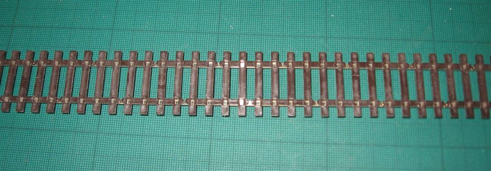
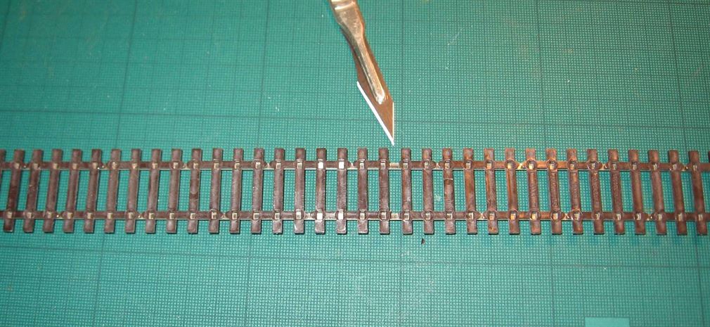
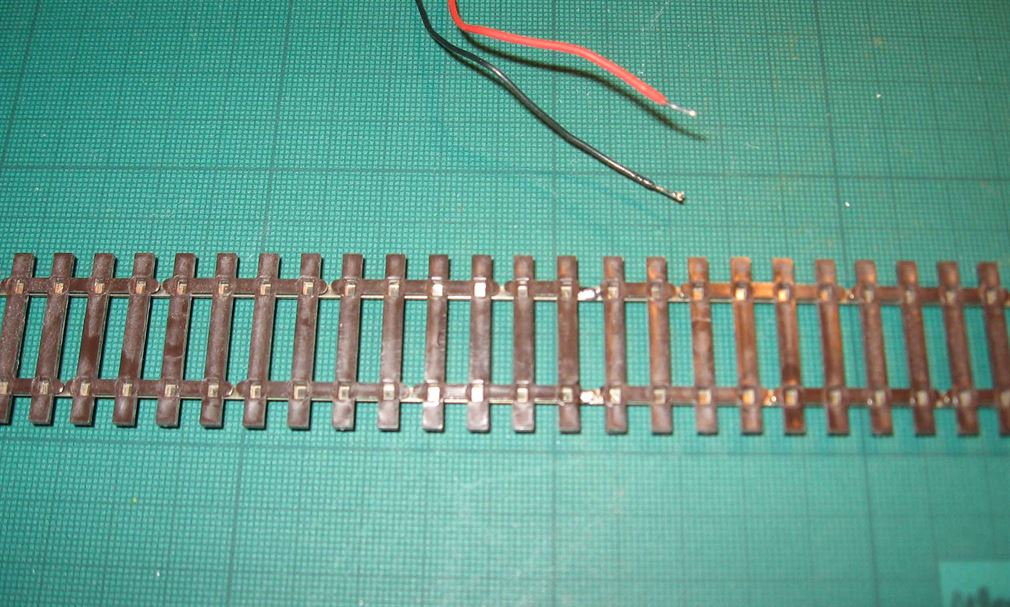
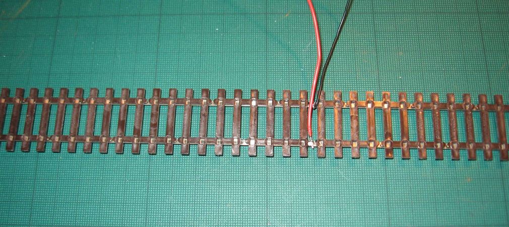
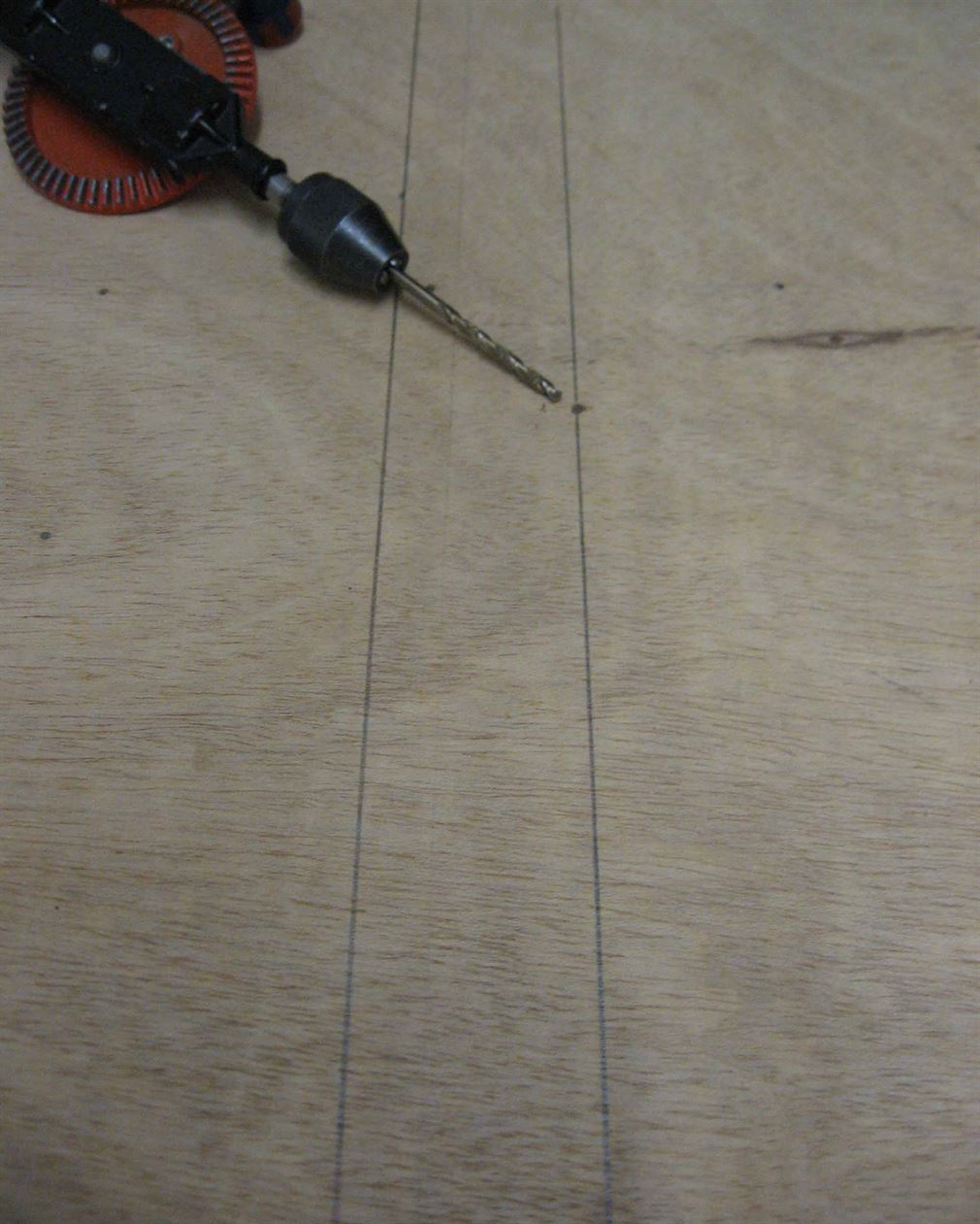
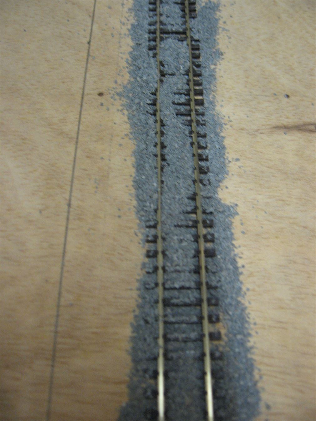
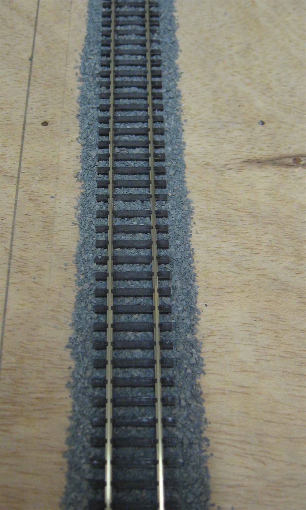
Below shows a complete sequence in dropper wire soldering (to the underside of rails) and the track being laid and then ballasted.


Click on a picture to view it larger.
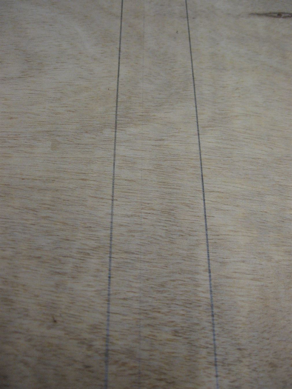
Above - Photo 1 shows the underside of a piece of Peco Code 100 track. Photo 2 shows the sleeper joining webbing being cut and removed. Photo 3 shows the rails undersides have been solder tinned and the two dropper wires insulation stripped and the wires tinned. Photo 4 shows the two dropper wires soldered to the rails undersides. Photo 5 shows the baseboard marked where the track centres are to be. Photo 6 a 4mm dia hole is drilled in the centre line. Photo7 The two dropper feed wires have been passed through the hole and the track laid into its final position. Photo 8 shows the ballast has been spooned (Teaspoon used as a mini shovel) over the track pending final brushing into place. Photo 9 shows the final track laid into position, ballasted and ready for a coating of bonding adhesive. Dilute PVA with water 30/70 and a couple of drops of washing up liquid or Meths to the mix to remove surface tension, then applied carefully with an old eye dropper or larger Pipette and allowed to dry untouched for at least 24 hours.
Carry on running in track wires until are all installed. This may (and will no doubt) include “through feeds” not actually connecting to any sections of track on that particular baseboard or area. Remember to keep recording each wire in the diagram book.
I don't recommend using rail joiners (fishplates) as a place for soldering electrical rail feeds onto. The reason is that the two abutting rails will be continually moving a little inside the joiner allowing expansion and contraction of the rails that are leading away from the joiner. This movement will ultimately introduce a high resistance 'HR' into the joint on one or both sides of the joiner. This is caused by the small movement loosening the joiner and dust particles etc in the air combining and making an almost invisible insulation between the two surfaces. Even paint, if the rails are painted with a rust coloured paint, can get inside the joiner and form a HR joint! This insulation prevents or restricts the flow of current from the joiner to the rail/s. The HR rail joiner often manifests itself in loco's running erratically or stopping for no apparent reason on a certain piece of track. So it is far better to solder feed wires onto the rails themselves, even if this means installing several wires series connected (daisy chain fashion) along the lengths of track being feed by that supply. Linking or bonding out the joiners is another option by using small sized flexible wires soldered onto the outside of the rail web and running from rail to rail across the joint.
The sketch below shows the problem and option mentioned above.
While the above drawing shows the two feed connections onto the rails almost at the joiners location in reality these feeds can be anywhere on the lengths of rail going away from the joiner.
Once all the track feeds are run in proceed onto running in the point motor feed wires. But firstly stop and have a well earned cuppa!
SWITCHES..… Various styles of switches can be used in model railway electrical controls but perhaps the most common switch to be found is the Toggle Switch often the smaller "Miniature" style. The rotary switch is also popular as this allows many switching contacts to make or break with the turn of a central shaft.
The Toggle switch is readily available in various contact formats and lever positions i.e. On-Off, On-On, On-Off-On or On-Off-On centre off spring loaded to centre off or even some that are biased to one position.
Below I have listed some various type of Toggle switch contact arrangements normally found.…
Switch Terminology....
'Poles' are the number of independent electrical parts within one switches body.
So a switch can have one or more poles. e.g. 'SP' means Single Pole - One electrical input. 'DP' is Double pole - two independent and isolated electrical parts within the switch. 'TP' is therefore Triple Pole or three independent and isolated parts within a switches body.
'Ways' are the number of electrical paths or outlets a switch has. So a 1 way is just a single on / off function connecting the input (Common) tag to the output tag or disconnecting the output tag when the lever is in the opposite position. So a 3 way switch would have three separate outputs from one common input i.e. the switch can be turned to any of three positions and each position connects that outlet with the common input terminal.
‘Throw’ is the number of electrical outlets connected to the common tag. A Single throw switch (ST) will only provide On / Off switching therefore the switch would only have two connection tags. While a Double Throw (DT) will make contact to either side of the switch dependant upon the toggle or levers position. i.e a DT switch will provide On - On to the common tag. It will have three terminals or tags and is sometimes called a "Two way switch" (Just to confuse matters!).
In all cases the use of the term C/O means 'Centre Off' when referring to switches.
Rotary switches offer many contacts and normally several positions or clicks of the rotary shaft (or knob when fitted). Typically these can be 4 pole 3 way to 1 pole 12 way, Now don't get confused here, 'Ways' are the number of positions a rotary switch can be turned to. So for example a 3 way rotary switch can be turned to any of three positions. While the 12 way can turn to any of 12 positions. So for example a 12 way 1 pole rotary switch can click or turn to 12 positions, but it only has one input (way) which is then connected to any of the 12 output positions selected. While a 4 pole 3 way can turn to any of 3 positions and it has 4 inputs (poles) that can give any of three outputs each! To confuse even a little more rotary switch can be supplied in ' Make before Break' or ' Break before Make' configurations! Mainly for model railway use the Break before Make style is the one needed, as we need to ensure the circuit being switched is disconnected before the next circuit is connected.
 toggle switch")
 toggle switch")

 or On/On contacts")
In Photo 1 above, a SPDT (Single Pole Double Throw) toggle switch or On-On type is shown. Photo 2 is a DPDT (Double Pole Double Throw) toggle switch On-On for 2 separate circuits while Photo 3 shows a 4P3Way (Four Pole Three Way) Rotary switch and Photo 4 is a Hornby SPDT On-On lever switch.
In both Photo's 1 & 2 the central tags are the armature (moving contact or common connection). The output tag (making contact with the common) is normally always opposite to the direction of the toggles lever. Hence - toggle lever to left the right and centre tags make contact, lever to the right the left and centre tags make contact. If the switch has a centre off position then neither of the outer tags make contact with the central tag while the toggle lever is centred.
In Photo 3 rotary switch, the four central tags are the four 'Ways' of the switch and the outer tags make the connection to the appropriate way.
Photo 4 is a Hornby On-On lever switch (SPDT). i.e. This does the same function as the switch in Photo 1.
Circuit Distribution. There are many times on the layout where one or a pair of wires are feed from a supply and then need to be split and distributed to various locations around the layout.
Consideration must always be given to the feed (Bus) wires size so as it can easily handle the larger current flows and any long wire runs where volt drop occurring in the feed wire may cause issues. Circuit protection should be considered too. This can be via a in-line fuse inserted into the positive feed after the Power supply or a self resetting circuit breaker both being of the correct current rating to protect the wiring and the power supply.
The simplest of these distribution connections can be a feed (Bus) wire that has had a small portion of its insulation stripped away and the sub circuit wires are then wrapped around the stripped feed wire and ideally the joint soldered. The joint once cooled is then covered with Insulating tape. This initial joint pre insulating is shown below.
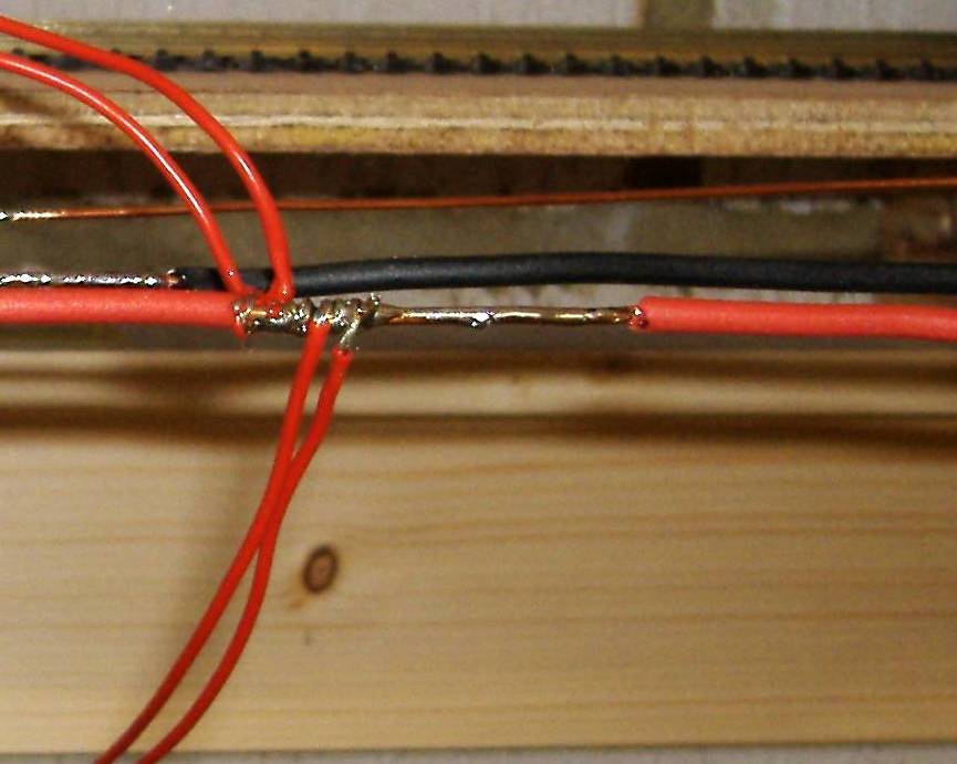
The picture above shows the main feed or 'Bus' wire with four sub circuit wires attached and soldered and is pending being insulated with some PVC tape .
The next easy method of use and no soldering is involved is to use a 12 way strip of terminal block connector or cut a 12 way strip cut up into the required outlets needed, but always allow some extra for future alterations!
Below shows a simple example of the Terminal Block idea where a 12 way strip is divided into 2 x 6 ways.
One other cheap common connector is the use of a two way piece of terminal block. Here a copper wire, ideally stripped from former mains solid wire, is bent to a U shape and inserted into one side of the block. The feed wire arrives on one terminal on the opposite side and leaves again via the other terminal. Onto the bare wire loop are wrapped and soldered the sub circuit wires.
All items appearing on this or any page of this web site are the intellectual property and © copyright of Brian Lambert. Unless otherwise stated.
You MUST NOT make available by placing them in any public domain area or in printed format any copies of Text, Image, Drawing or Video shown on this web site.
No item as listed above should be used, copied, linked to or forwarded by any third party without firstly obtaining the written permission of the web site owner - Brian Lambert.
You may freely and for personal use only, copy or print any areas.
You may refer to this web sites page electronic address detail (URL) in any other media - printed or electronic. Any such referenced URL should commence.... https://www.brian-lambert.co.uk/
Brian Lambert accepts no responsibility for any item appearing on this or any other page of this web site.
All items are given in good faith.
By visiting this web site you agree to accept and abide by all the condition shown above.