www.brian-lambert.co.uk

West Haven.
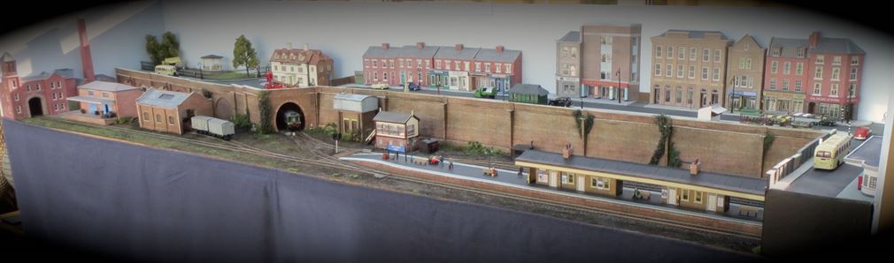
A micro layout in “OO” and fully DCC
West Haven was sold to a new owner in the summer of 2016
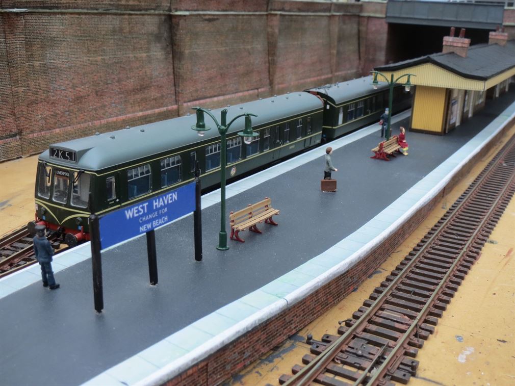
Early in 2014 a decision was made to build a small “OO” scale layout. The criteria was that whatever was built should fit inside a standard size car and be easily transportable and simple to erect by one or two people. It would also be totally DCC operated. All track is Peco Streamline code 100.
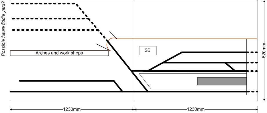
Simple baseboards were constructed using plained timber and a MDF top.
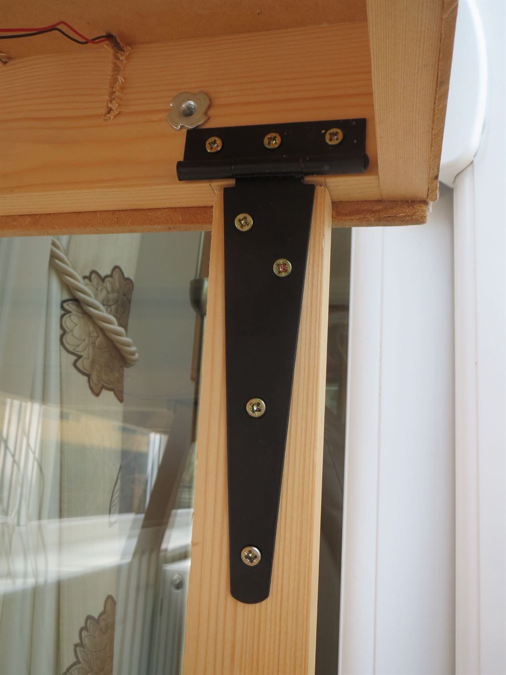
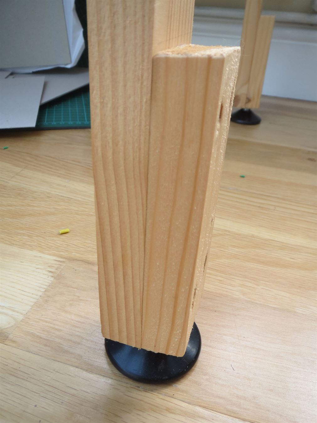
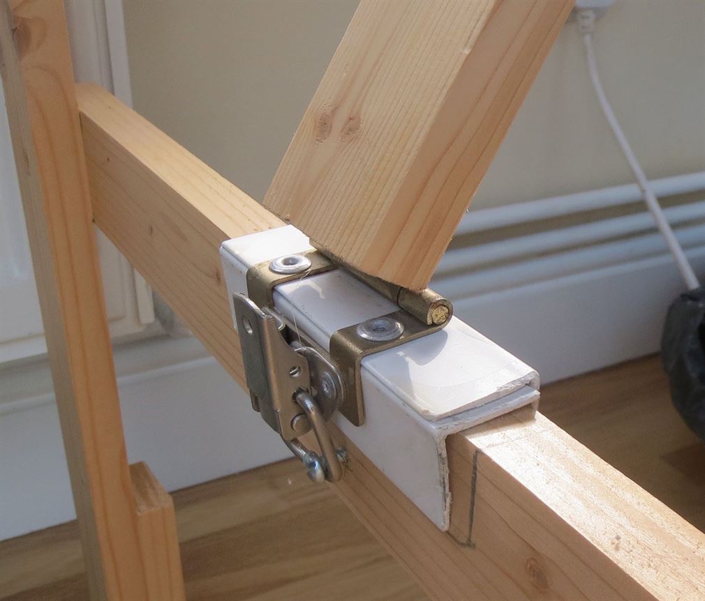
The timber framing chosen was 69 x 18mm PSE with a top of 6mm thick MDF. Once the basic sections were assembled and fitted together, two Cabinet maker dowels are used to ensure accurate board alignment every time the two boards are fitted together. Two suit case style toggle latches are used to pull the two boards together and keep them tightly joined. Legs to support the two boards were fashioned from 21 x 44mm PSE timber. These are hinged from the supporting frame timbers by the use of Tee shaped hinges, adjustable feet are fitted to all legs to enable uneven floors to be catered for. The right hand baseboard has two sets of legs while the left hand board only has one set fitted on its left hand end. This enables simple and quick setting up. The right hand board is erected first then the left boards legs are locked down and its then connected to the right hand board and the toggle latches connected and locked closed. So as the left hand baseboard is piggy backing onto the right hand board. Support legs have been made to give a working height to the baseboard surface of 1000mm. A 6mm MDF backboard was cut so as it forms a sort of ‘U’ shape on three sides. This stands 320mm above the baseboard top. It was sealed and then given two coats of emulsion paint in a sky blue colour. Access slots have been cut in the backboard at just above baseboard level to allow easy rail cleaning, rectification of any derail stock inside the tunnel/hidden areas and to allow wiring to the items on the street scene above.
The rear street scene itself is raised above baseboard level. This is supported on a light timber framing of 12mm square Pine PSE timber and covered in 3mm MDF.
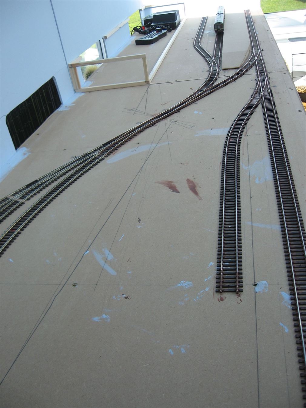
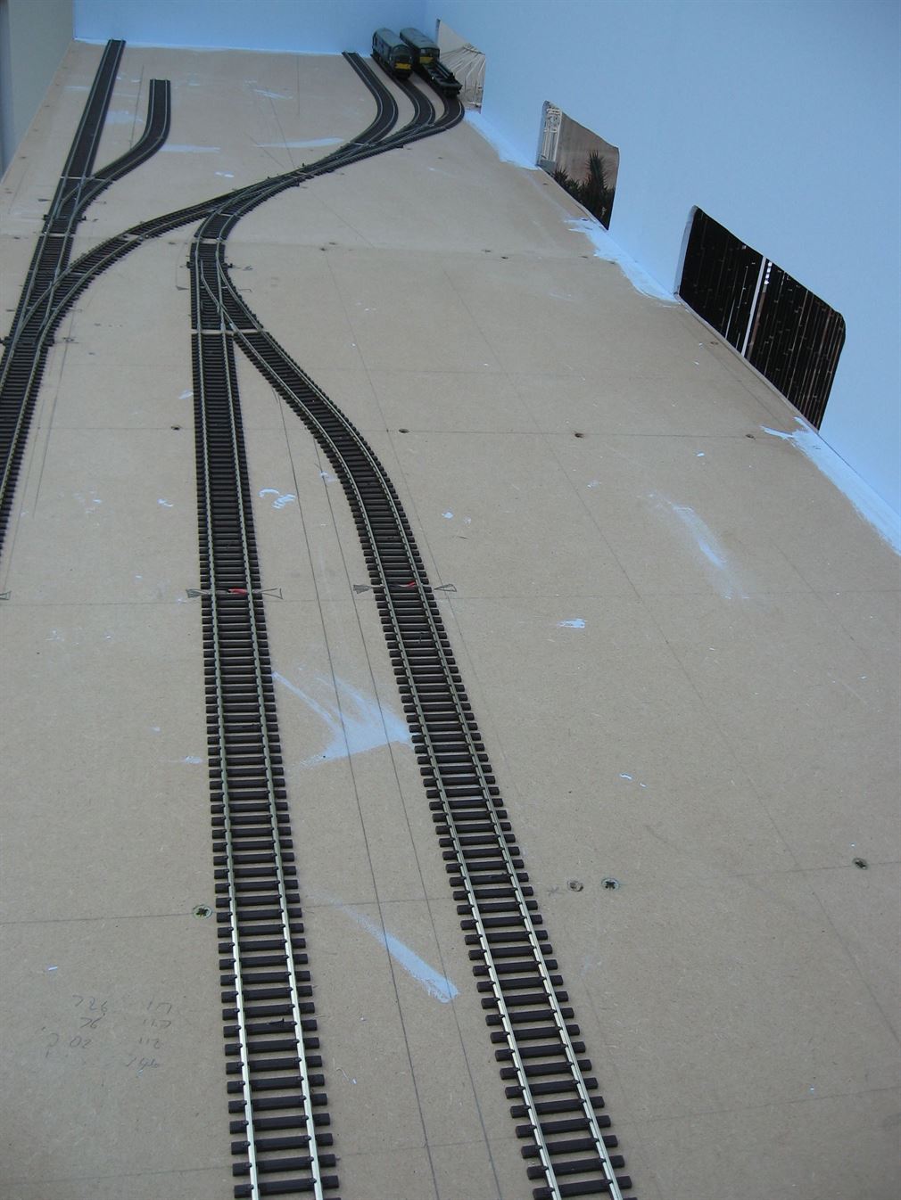
Having completed the carpentry, focus turned to the placing of track items onto the baseboard and ensuring that no point sat directly over the board joint or that the points stretcher bar (Tie bar) was not located over or very close to any underside timber cross beams, as this would cause problems when fitting point motors, all of which are under baseboard mounted Seep PM1 type. Have ‘jiggled’ the basic plan, all the pieces of track were pre wired with dropper wires. Each point and every piece of track was fitted with a pair of droppers, in my case one red and one black, these being soldered to the rails underside. Due to the layouts small size and the DCC bus pair of wires running underneath very close to the track configuration, I opted to use 7/0.2mm equipment wire for all droppers as no one dropper wire has an overall wire length exceeding 300mm. All points being Peco code 100 Electrofrog have been fully converted to give the best possible power transfer through the point. This is explained on the DCC pages of this web site here…. Link to DCC page 1
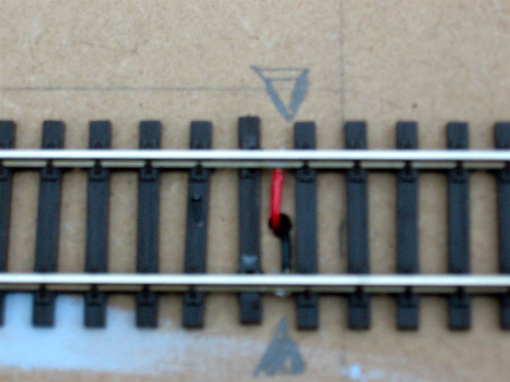
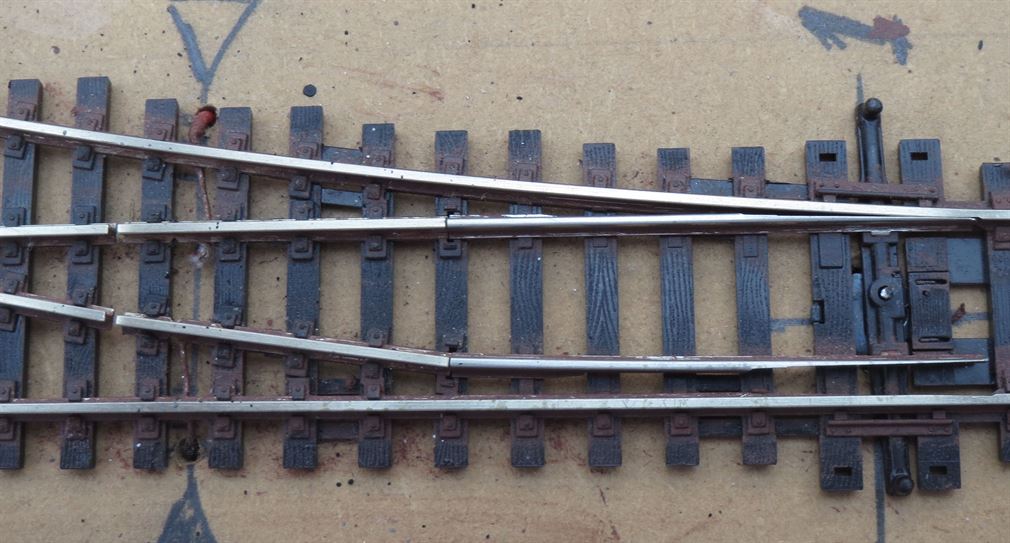
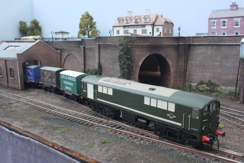
While soldering droppers to the rails underside on every piece of track and point may seem excessive I wanted to ensure no reliance was placed on any metal rail joiners passing power or DCC data rail to rail. The rail joiners (fishplates) only keep the two abutting rails in register. The track was laid directly onto the MDF surface, which previously had been given two coats all over - top, bottom and all edges of dilute PVA glue to thoroughly seal it. The track then being pinned down temporarily with the aid of fine Peco SL-14 track pins pushed through the sleepers at approximately every 120mm. The pins being only pushed in for about half their length then bent over by 90 degrees to lay along the sleeper so as later they can be easily removed. A bent over track pin can just be seen in the straight track section pictured below, its inserted into the second sleeper to the left of the two dropper wires. The picture of the point shows the two dropper wires soldered to the underside of the points outer stock rails and linking to the adjacent closure rail, the two closure rails have a gap in both rails and the two factory fitted link wires that bridged the gaps underneath have been removed. Note though that this work can only be carried out on points that have frog polarity switching employed.
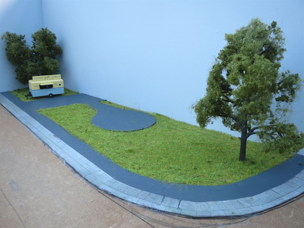
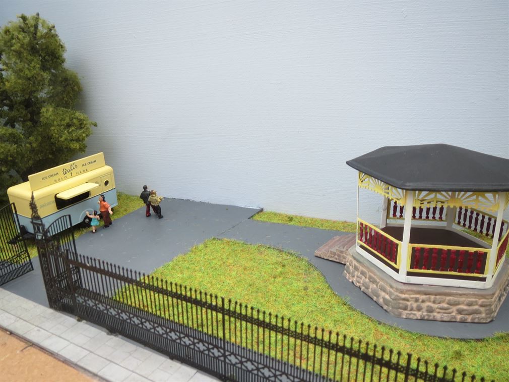
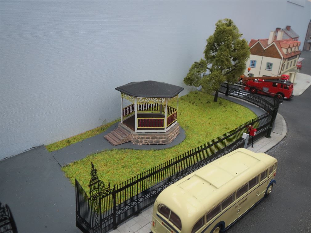
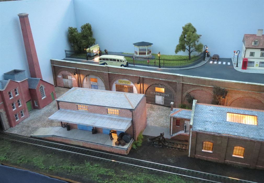
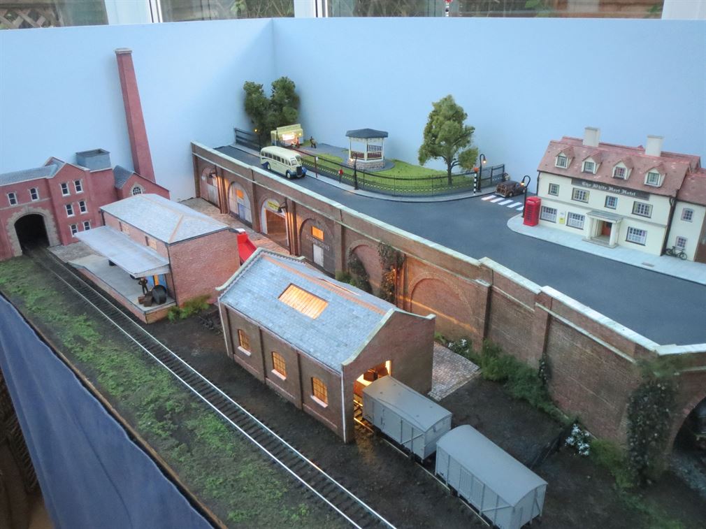
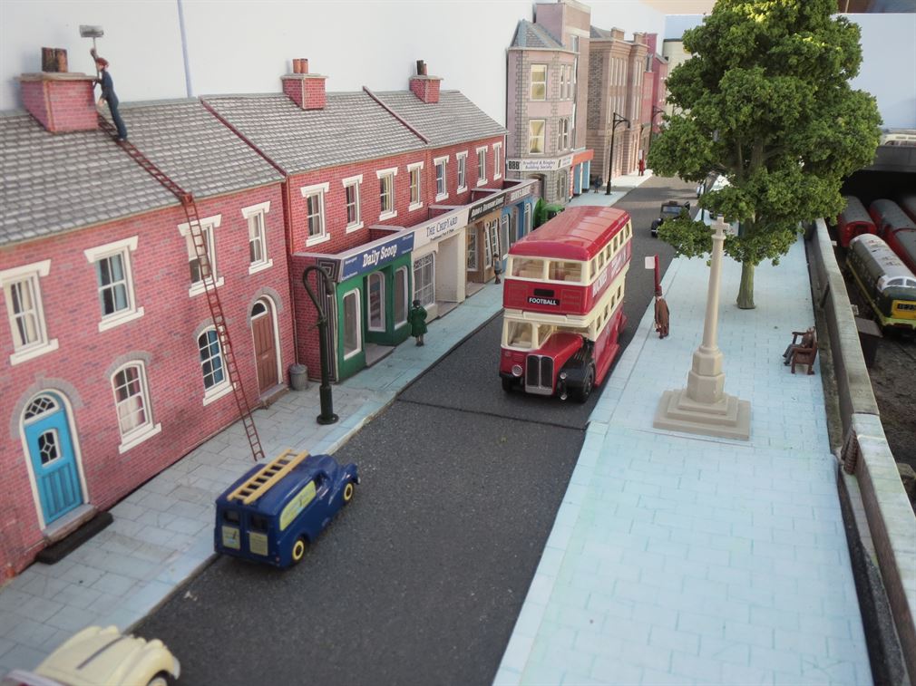
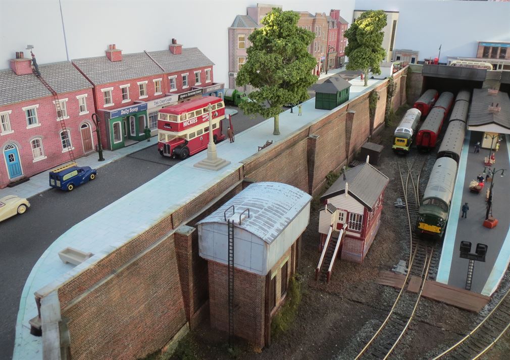
A road surface was marked out onto the upper level board, the road area being later sprayed with a textured stone finish paint. This, once fully dried, was sprayed with varying mixtures of grey to represent tarmac. The pavements etc being masked off prior to spraying to prevent over spray effecting them. In the left hand corner a park scene was created. Paths around the parks perimeter and leading in from the main gates were fashioned from 2mm card, painted a dark grey on the parks side and covered in Scalescenes paving on the road side. This was glued directly onto the MDF base. Then static grass was PVA glued to the remaining area of board to represent the parks grassed areas. An ice cream sales caravan was sited near to the gates and a bandstand added to break up the scenic. In addition two large trees where planted, The outer perimeter of the park was enclosed in a wrought iron fence and suitable park entrance gates added. These were all from etched brass frets that were initially sprayed with car primer paint then once dry spray painted with a satin black paint before being cut from their frets and fixed to the high level board. A small number of people were added to the park area. More still need to be added!
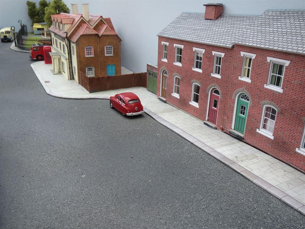
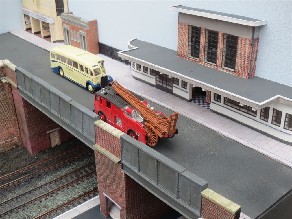
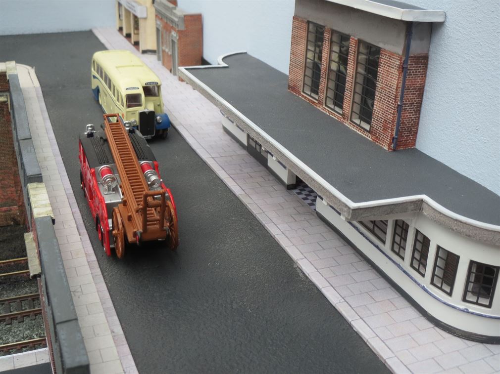
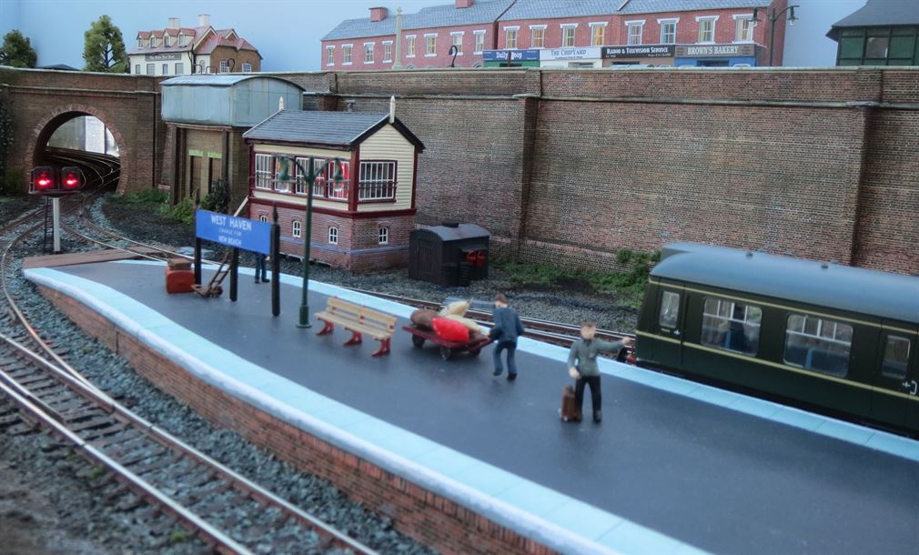
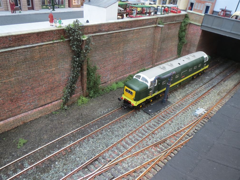
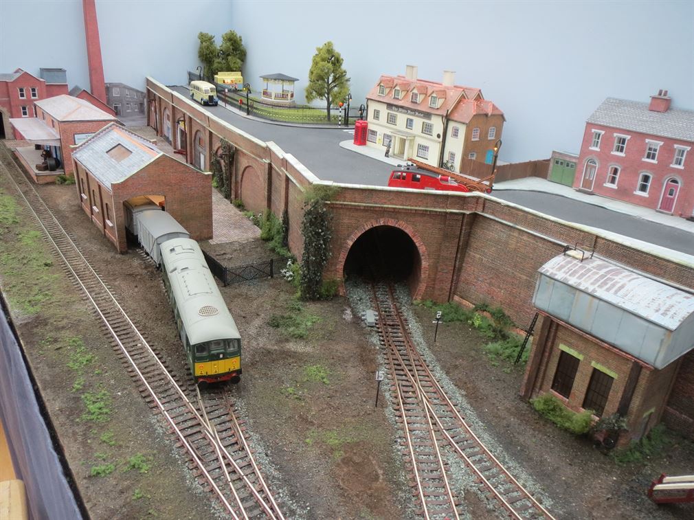
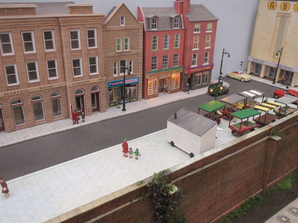
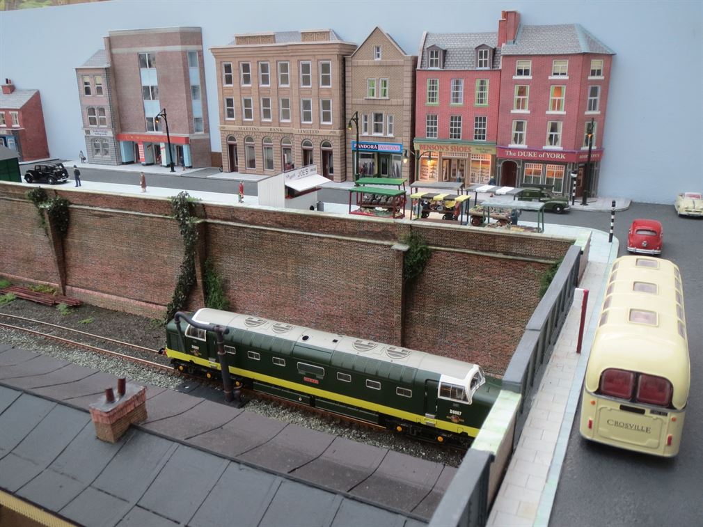
Further along from the park on the high level area is a hotel/pub then a row of houses and some smaller local shops. After this comes the larger shops and banks etc. Approaching the main road T junction, opposite is the ABC cinema and turning right leads onto the railway over bridge where the stations entrance is located, together with a public WC and bus stop. All the buildings except the station entrance and the WC are from card, the WC and station are from the Bachmann Scenecraft low relief range of buildings. Pavements have been produce as before from 2mm thick card covered in Scalescenes paving. LED lit street lights are being installed. Opposite the high street shops on a wide pavement area is a small barrow market, a tea kiosk and further down the pavement is a taxi mans rest, then the war memorial and a disused horse watering trough.
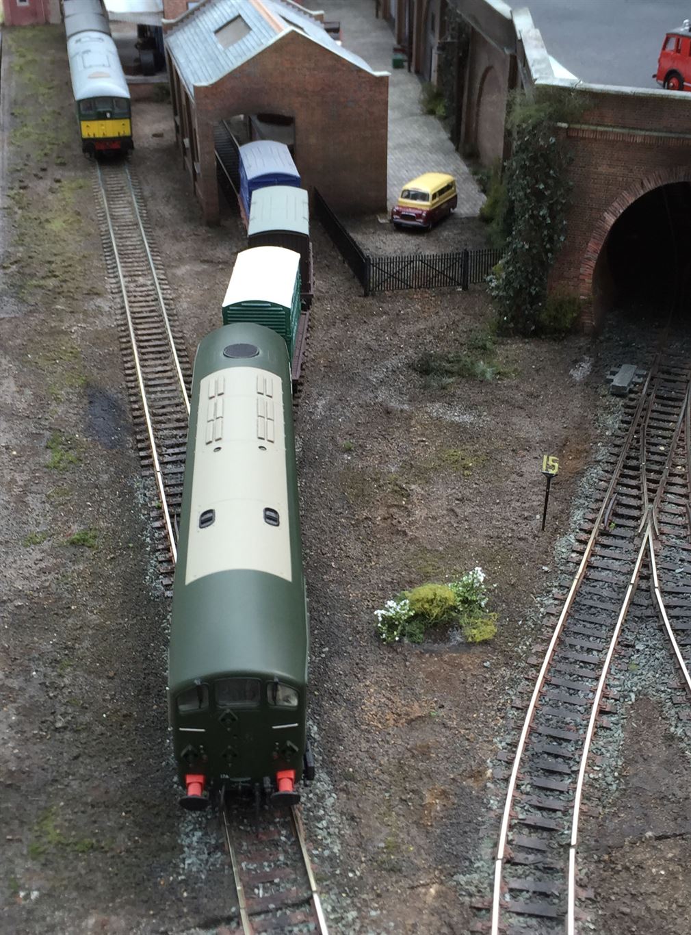
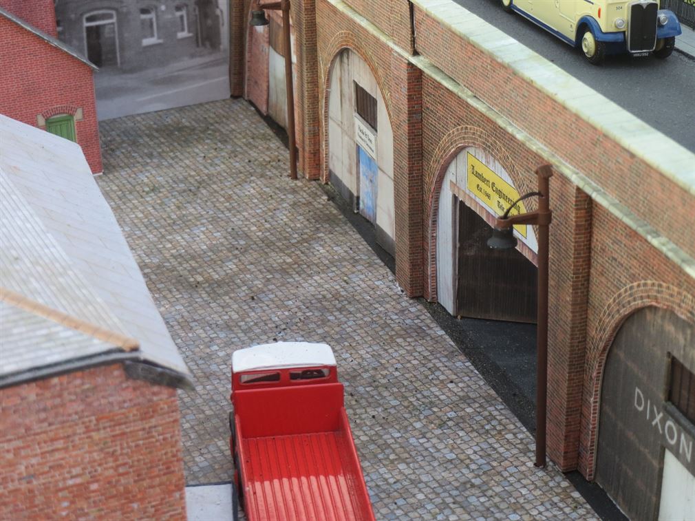
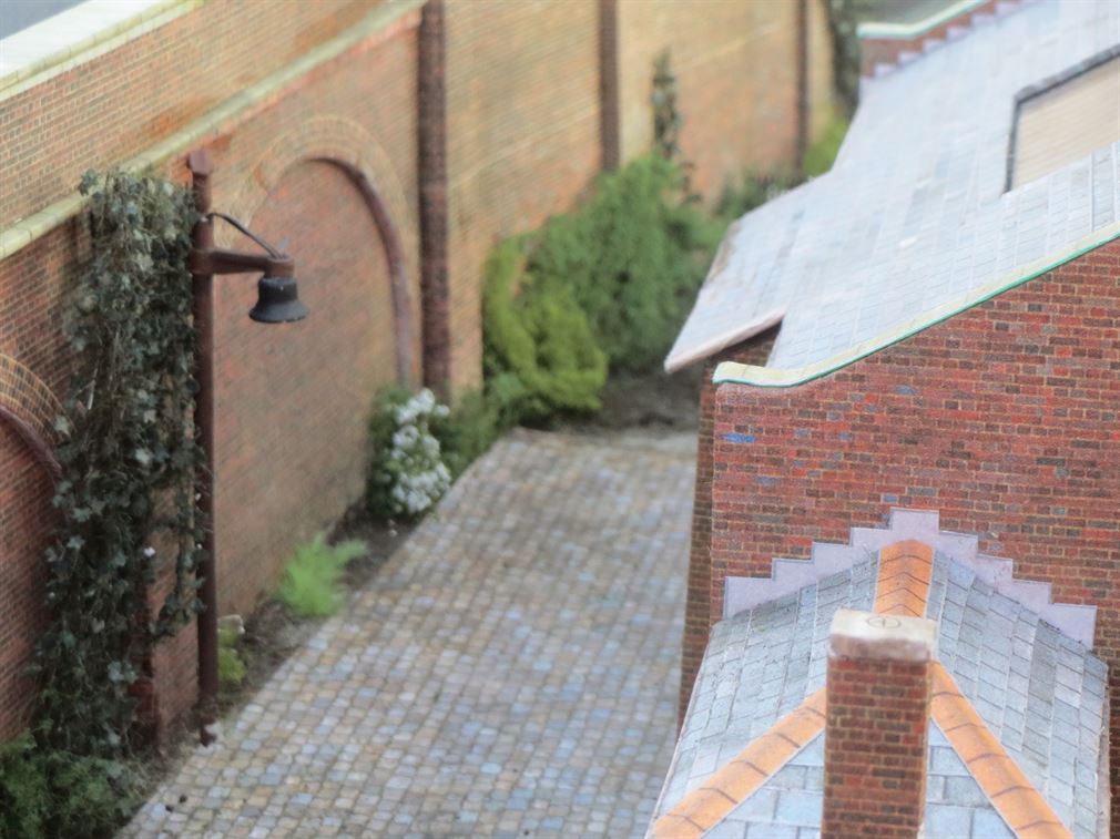
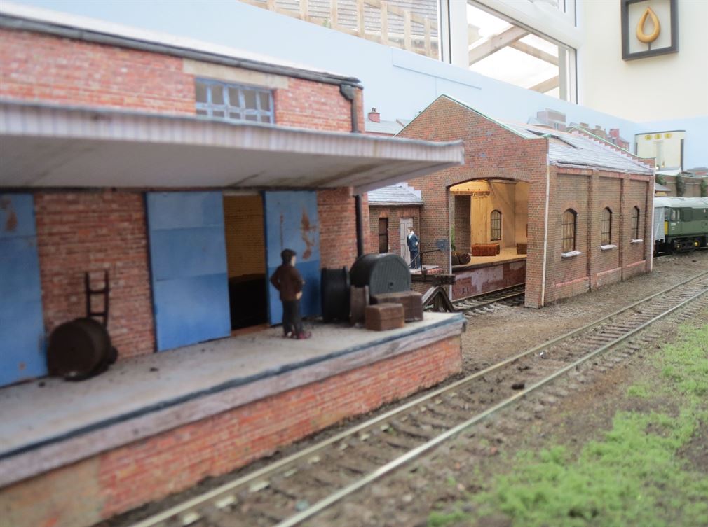
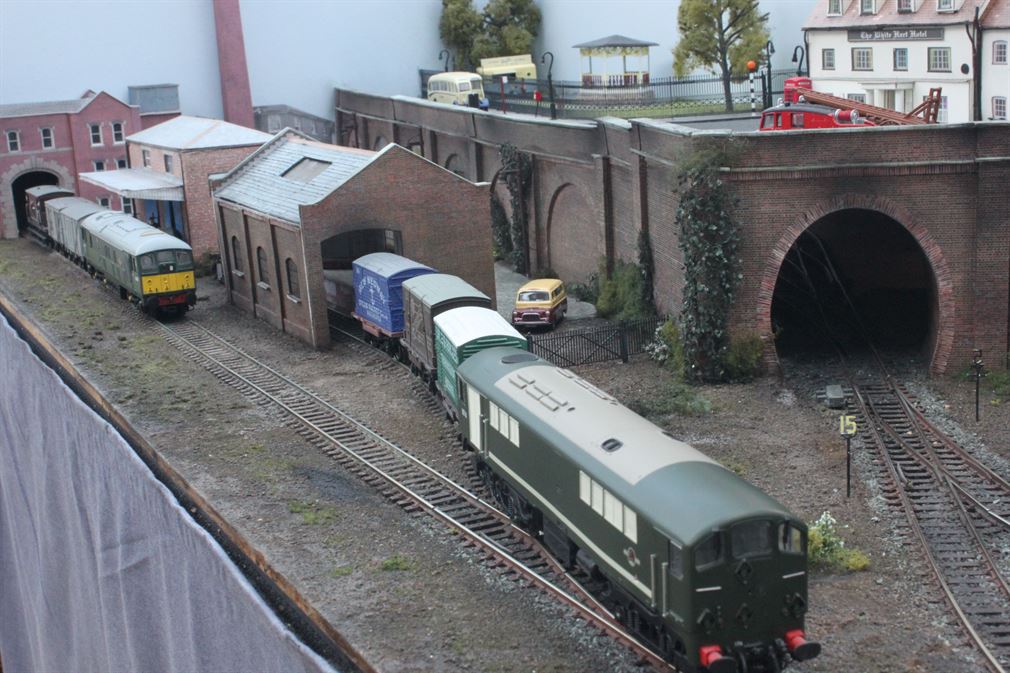
To support the high level street etc. a series of retaining walls was constructed. On the right hand board the walls are produced from Scalescens retaining walls These are downloaded from the Scalescenes web site as a .PDF format, saved and then printed as needed on a home ink jet printer. The A4 printed sheets are then sprayed with artists matt varnish sealant or when available an Inkjet print sealant which is very similar to artist spray. The sheets are then glued with a Pritt stick type of paper glue stick onto the correct thickness of cardboard. This being 200gm card, 1.0mm and 2mm thickness as required by the kits instructions. Once dried the appropriate parts are cut from the card with the aid of a scalpel knife, the parts then assembled to form a strong card structure. On the left board there is a single line tunnel portal which leads to the hidden under street three road storage lines. Also on this board are a series arches some of which have been opened up into workshops. A few traders have residency in these - first one is to rent, then comes Heale & Sons Painters and Decorators, Lambert Engineering and finally Dixons & Sons. The remaining two arches are bricked in. Two of the three occupied aches have lighting installed and in one a welder is busily working. This uses a high brightness white LED which is rapidly flashed on/off for a pre set period to represent the welding arc and then stops for a time before recommencing again. This is made from a home made circuit which is shown on the Electrical Page 2 here
To the right of the tunnel is a water tower which supplies water to the stations single loco water column and to the station in general.
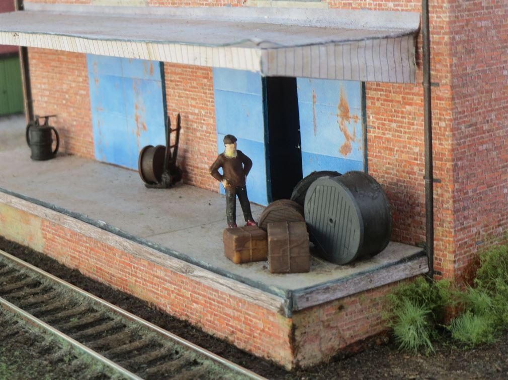
Three new buildings have been constructed to the left hand end of the layout, a goods shed, warehouse and a factory. The goods shed and warehouse are made from Scalescenes download kits while the factory entrance and boiler house are a Metcalfe building. A cobbled street area to the rear of the goods shed and warehouse has been laid and three LED lit post style lamps light the cobbles after dark. The warehouse and goods shed both have internal detail added and LED strip lights internally per building. The ground area around these three buildings has been created to represent generally rough ground. The factory gives a scenic break to the end of the layout and the cobbled road. Some more detailing is now needed for the arches workshops and an open back lorry is to be made up with a load that will fit in with the warehouse, whose trade is in wholesale electrical cables and associated items.
With much of the scenic work completed and a few people painted and added to the street scene, the rails were fully cleaned and DCC loco running commenced. All has been proved to work correctly. As my chosen DCC accessory point decoders (DCC Concepts ADS-S8 and AD-S2) allow additional panel switch operation as well as direct DCC operation, I am beginning to build a simple mimic panel that will be permanently fitted into the rear of the lower portion of the back scene - fitting in below street level. It will contain the track plan with eight point operating switches and point direction LEDs.
West Haven was sold to a new owner in the summer of 2016
All items appearing on this or any page of this web site are the intellectual property and © copyright of Brian Lambert. Unless otherwise stated.
You MUST NOT make available by placing them in any public domain area or in printed format any copies of Text, Image, Drawing or Video shown on this web site.
No item as listed above should be used, copied, linked to or forwarded by any third party without firstly obtaining the written permission of the web site owner - Brian Lambert.
You may freely and for personal use only, copy or print any areas.
You may refer to this web sites page electronic address detail (URL) in any other media - printed or electronic. Any such referenced URL should commence.... https://www.brian-lambert.co.uk/
Brian Lambert accepts no responsibility for any item appearing on this or any other page of this web site.
All items are given in good faith.