www.brian-lambert.co.uk
 (2017_08_14 09_17_54 UTC).jpg)

Digital Command Control - DCC
Page 1
Hornby, Bachmann, ZTC, Digitrax, Lenz, Fleischmann, MRC, NCE, Zimo, ECoS etc
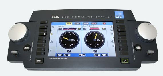
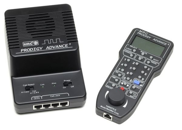
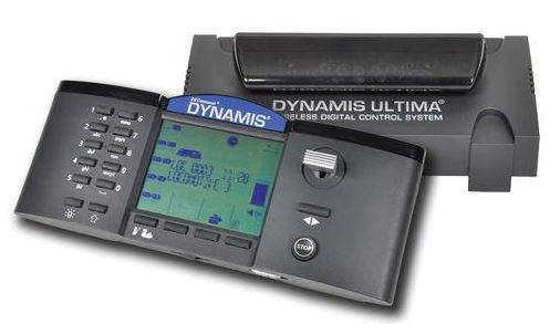
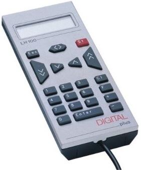
Some examples of DCC systems....
.jpg)
.jpg)
All pictures are courtesy of the individual manufactures
Comparison of the two methods of train control..
Normal DC systems (These could be called Analogue' control systems) to move a locomotive we proved nominally between 0 and 12volts dc to the rails. When full voltage is supplied then the loco will move at the fastest speed the motor can muster. If we want the loco to run at half speed then the supplied voltage is reduced accordingly.
e.g.. Half rail volts equals half speed, three-quarter full volts equals three-quarter speed etc (this isnt quite correct, but its near enough for this example).
DCC systems supply full volts (typically 14 to 16 volts ac depending on the system used) to the rails all the time and each loco has it own on board DCC decoder fitted (Micro chips on small circuit board). The decoder is in constant connection to the rails via the locos wheels. Digital command signals are continually sent out by the operators DCC controller and are received by all the decoders in all the locos on the tracks. Each locos decoder is given a separate identification number called an address number. Normally only one decoder/loco will respond to the unique address number and then its decoder will supply the commanded voltage to that locos motor e.g. move forwards at quarter full speed or reverse at 1/20th full speed etc. The motor receives from the decoder full volts for half the time for half speed running or full volts for three-quarter of the time will give three-quarter speed etc. This is known as a pulsed power supply For those who noticed this paragraphs opening comments re 14 to 16 volts ac being on the rails all the time. This is correct, but the 'ac' isn't a typical sine wave (RMS) ac it is more of a hybrid square wave form. The decoder uses the track power ac voltage and converts it into dc to feed the motor and any function outputs e.g. directional lights, smoke units or sounds etc. Decoders as supplied new should all come with a default address number of 3. This address number should be changed by the user to another number once the loco has been proven to work correctly on the default address number. Often this is the last two, three or four digits of the locos running or cab number are used. e.g. Loco 37172 could become address number... '2', '72', '172' or even '7172'. It should be noted that some decoders only support two digit addresses while others depending on make support up to four digit addresses. Note: Most decoders use the two digit address range is 1 to 127, while three/four digit addressees can be between 128 to 9999. While I appreciate 100 to 127 is technically a three digit range, DCC decoders use this range and still call it a 2 digit address, due to the way the address is configured!
Typical Basic DCC arrangement
.gif)
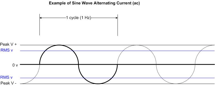
What is the DCC voltage and is it like ac or dc? A DCC voltage is not at all like mains power alternating current (ac) where a sine wave curves between zero volts and maximum volts positive (Known as the Peak volts) and then curves back down to pass through zero volts and enters the negative portion of the half cycle again reaching the negative peak volts before starting to climb back to zero again. In the UK and much of Europe this is occurring at 50Hz (50 times a second) while America and Canada use 60Hz frequency. Example of one cycle (1 Hz) of a sine wave ac frequency...
.gif)
But DCC is different. The wave form consists of packets of information coded into a dc wave. This really is best perhaps described as 'Pulsed dc' but technically its still an alternating current (ac)! Confused?


So the DCC transmitted by the command station contains a voltage that is a modulated pulsed wave and at the same time those pulses are a digital means of sending data via long or short pulses. Known as Binary 1 or 0.
The length of time the voltage is applied in each direction provides the method for encoding data. To represent a Binary 1, the pulse time is short nominally 58µs (microseconds) for a half cycle, while a 0 is represented by a longer period nominally at least 100µs for a half cycle. This is transmitted to the rails and decoders at a frequency of around 8KHz (8000 cycles/second) or putting it another way - 8000 bits per second. The Binary 1 and 0 are received by all decoders on the layout but only the one with the correct address number will respond to the stream of data being sent.
The system of motor voltage control used by the loco decoder is called Pulse Width Modulation and a simple example of four typical states of modulation are shown below - 1/4 speed, 1/2 speed, 3/4 speed and full... While the Full speed is shown as a continuous line, in fact it is being switched on and off rapidly.
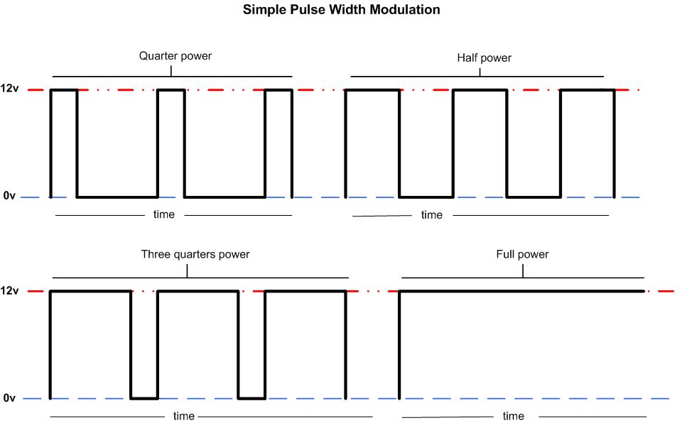
Many modern decoders are now using high frequency PWM for the motor drive, which eliminates the 'Hum' often heard in older decoder / motor combinations. These are often referred to as "Silent drive". Their operating frequency being in the 20,000 to 40,000Hz (20KHz to 40KHz) range.
So every loco on the DCC controlled rails has a decoder fitted, they all receive the data commands simultaneously, but only the decoder that has the unique digital address assigned to it will respond to the digital data signal being sent along the rails at that time. All the other locos decoders will ignore the commands and continue doing whatever they were last instructed to do! i.e. Those that have been previously told to 'Stop' or have not received any digital instructions since powering up of the DCC system will remain stationary. Once the correct decoder has seen the data arriving, it will act upon the commands and operate the device it’s connected to accordingly - motor, lights, sounds etc. Once it has been set, the device will remain at that setting until another unique command is received. What can happen now is that the operator can call up the address number of another loco’s decoder and send a digital address to allow this loco to move off. The first loco continues to run at its last setting. Hence we can now operate many locos simultaneously on the same rails. although we actually only drive one at any one time, as the others are doing what they were last set at to do. e.g. we can set the main line train running and then call up a loco in a siding and carry out some shunting etc while the first loco continues to run uninterrupted. Of course now we can have one loco stopped in say a platform and bring a second loco right up to the stopped one and even couple the two together without the first moving or the need of special isolating track sections. The two locos can both be set to run coupled together if wished, which is called a 'Consist' (An American name for what is know as double heading in the UK) and both locos motors are set to be controlled by one temporary address number.
There is normally an “All Stop” button provided on the controller or console for any emergency! This will stop everything and once the problem has been resolved you will need, in most cases, to restart each loco again in turn.
DCC not only allows you to control many locos at once it also offers the opportunity to control signals, points, train lighting and on-board sound effects too. Add to this, in some systems, the option to have your computer running the railway and you can have a total train control system. Hence Digital Command Control!
.jpg "Typical Track Rubber")
.jpg "Peco wheel cleaner and scraper set")
.jpg "Trix powered wheel cleaner")
.jpg "Fibre Pencil")
I recommend not to rely on ‘push in’ electrical connections (Track power connectors and rail joiners) Solder the power wires directly to the outsides or underneath of the rails and seriously consider running a 'DCC power bus' or 'Bus main' (two heavy gauge wires) around the under side of the layout and tap off this as many times as possible to feed sections of track. By keeping the locos wheels clean and don’t forget to clean all the rolling stocks wheels too as these equally deposit dirt onto the rails, improved running will result. While the above is aimed at the DCC user some of these good practice items should be observed by the dc user too.
.gif)
To improve DCC operations it is recommended that the 'Bus main' pair of wires (I’ll call it a 'Bus' from here on) is run around the railway. Onto this bus are connected the running rails of all the tracks via 'Dropper' wires. The bus will improve operations many fold. Any problems such a high resistance metal rail joiners (fishplates) will be overcome, as will an improvement to the volt drop problem on larger layouts. Some advanced DCC systems require data to be returned back to the control unit so these systems use an additional data bus, these can have as many as six individual wires transferring data back and forth! But for the time being I’ll leave this detail and I'll only be concerned with the bus (Power bus or bus main).
Discussions continue to take place as to whether or not the bus should be in a ring formation (Ring is where each wire starts and ends back at the same place and is connected together to make a continuous ring/loop circuit) or Radial configuration. Both methods seem to work equally well. I haven’t used a ring preferring a radial bus circuit and I haven’t encountered any problems. Many DCC users opt for the 'Radial' or even a 'Star 'configured type of DCC bus A Radial bus being a pair of wires that start from one location and run out to the furthest point and terminate there.
A Star bus being a group of bus wires that all feed outwards from one place and each is a radial circuit.
In the drawing below are shown three simple examples of Radial, Ring and Star types of bus wiring.
.gif)
When designing your DCC Bus always try to arrange for the feed wires from the Command unit (console) to be as centrally as is practicable along the bus wires length. Or if using a star formation, make the stars central connection place the input from the console and try to arrange each leg (pair of bus wires) radiating out from the central point of the star to be as equal in wire run length as is practicable.
Once the bus has been installed, connect the DCC base unit’s track output terminals onto the bus, if necessary use a suitably large size of flexible wire e.g. 32/0.2mm or larger if it will fit into the units terminals for this.
On longer bus wire runs it may be helpful to lightly twist the bus pair of wires into a figure of 8 formation. About 8-10 or so twists per Mtr should be ideal. This should helps overcome any induced interference, cross talk etc occurring in the bus pair of wires.
Terminate all the free ends of the bus wires into two-way terminal blocks or similar, to ensure they can not make contact with each other and to give support to the bus wires at their very ends.
Now connect all the rails to the bus, ideally solder all connections onto the bus and the rails to ensure reliable data and current flow (Details of how to do this are shown further down the page). However, the use of 15amp type terminal strip blocks can be used at locations where soldering isn't considered easy or needed. Simply, we now have a reliable bus (power & data highway) which our locos can pick up power and data commands from via the rails connected onto the bus wires See the simplified layout for a DCC bus below. Note; the console is shown roughly mid way along the bus wire, but it can be connected anywhere off centre along the bus wires length…
The above drawing is very simplistic and is not meant as an actual design of track or railway. It is purely to show how a bus is connected from the DCC control unit via the two 'Bus' wires to the running rails. Note: All the points shown in the above are Insulated frog type.
Only one DCC console should ever be connected to the rails or bus. Further hand held controllers called "Throttles" or "Slaves" can sometimes be used, but this depends on the system. Where permitted these are connected to the main console via a special data cable - often an RJ12 connector is used. They are not connected directly to the rails or the DCC bus . Also never mix on the same rails a dc analogue controller with a DCC system. Fatal results will occur to one or both systems!
On long bus wire runs or where poor DCC performance is being noted a 'Bus Filter' circuit (occasionally incorrectly called Terminators) may help stabilise the data signals flowing in the DCC Bus wires. The filter can be made from a 0.1µf ceramic capacitor and one 120R to 150R OHM 2 to 3 watt resistor. Example items from UK based Bitsbox.co.uk 1 x CC100N 0.1µf Ceramic capacitor and 1 x PR023 150R 3 watt or alternatively 1 x PR120R3W 120R 3watt resistor. One filter circuit is to fitted at each end of the bus, so normally two filters would be needed. They are soldered wire end of resistor to one wire of the capacitor (both components are reversible so it doesn't matter which ends are jointed) then the free end of the resistor is connected to one bus wires end and the free wire end of the capacitor is connected to the other bus wires end. The can be (ideally) soldered to the bus wires or the previously mentioned terminal blocks used as their connection.
In the three pictures below the basic assembly of one filter is shown. Photo Filter-1 shows the components. Note the Heatshink tubing is not necessary if the filter components can be prevented from touching anything else when installed on the end of the DCC bus pair of wires. Photo Filter-2 shows the capacitor and resistor soldered together. Photo Filter 3 shows the two components with the heatshrink tubing shrunk down around them and are ready to install onto the DCC bus wires.
.gif)
.jpg)
.jpg)
.JPG)
The basic idea of the filters connection to the DCC bus is shown below....
Note: Shown are the use of two terminal block connectors but the filter to bus wire connections can equally be soldered if wished.
.gif)
Having installed the DCC bus around the layout in suitable sized cable, there is now a need to connect the bus to the rails. These wires are called 'Droppers'. This I recommend being carried out using 16/0.2mm or 7/0.2mm flexible wire in the same two insulation colours as the bus itself e.g. red/black or brown/blue etc. Note; I recommend if using the smaller 7/0.2mm wire then try to keep each dropper wires total length to around no more than 300mm. Solid copper wire extension droppers from the rails to below baseboard can be used and then solder or use terminal block connectors that join the flexible dropper wires onto these extension droppers, where necessary cutting the extra length of the solid dropper wire off once all has been securely soldered. However, you can solder the flexible dropper wires from the bus directly onto the rails if wished and is a better connection!
As stated, one method of connecting the dropper wire is to directly solder it to either the rails outside or if the track hasn't been laid then the dropper can be soldered to the bottom of the rail making it virtually invisible.
.gif)
 (2017_01_23 23_11_49 UTC).jpg)
The two drawings below show an alternative method using solid wire extension droppers then connecting onto the flexible dropper wire that runs off to the DCC bus.
 (2017_01_23 23_11_49 UTC).jpg)
 (2017_01_23 23_11_49 UTC).jpg)
Above pictures show solid copper wire droppers pre bent to shape before soldering. In the second picture after soldering to the outer web of the rail on what later becomes a hidden section of track.
The final connection is from the bus wire to the base unit or consoles output terminals, here use a minimum of 32/02mm2 wire. The actual place of the connection on the bus is normally around the mid point in the bus wires run, making a sort of 'T ' or star shaped connection. The upright of the T is the feed from the console and the cross part of the T being the bus wire. This main feeds actual connection place onto the bus can be made more towards one end of the bus wires if its more convenient.
 (2017_01_23 23_11_49 UTC).jpg)
 (2017_01_23 23_11_49 UTC).jpg)
.gif)
The following shows the three basic methods of making the connection between bus wire and the dropper wire.
First shows the stripped bus wire and the dropper is then twisted and soldered to the bus wire, once cooled the joint is wrapped in insulating tape
Middle shows a joint made with a terminal block connector. Last shows the use of a Snaplock connector. (this is my least favourite method of connection).
Programming Track... Most systems require a length of ‘Programme track’ to be available for setting up the on board decoders in each loco. This special track is often powered from a dedicated programming output on the base unit or console. It allows each loco’s decoder to be programmed without causing any changes to the all the other existing decoders already in locos on the main tracks. Where the console unit has a special Programming output it provides a lower current supply to the rails during programming mode to prevent decoder burn out should it not be installed correctly or the loco is defective etc. However, it should be noted that not all consoles provide a separate programming output.
.gif)
The second diagram below shows a console with a separate Programming track output and how the end of a siding can be wired via a DPDT switch. If wished a centre off toggle switch can be used. So then the siding end would have the option of being Normal DCC powered, Off, or a Programming track section which is isolated electrically from the rest of the layout. This means a loco can be driven to the sidings end (see Caution note below) under normal DCC control, the switch changed over, the loco is then programmed to whatever is required, the switch flipped back to normal and the loco driven off without ever having to leave the rails or be touched. CAUTION Never allow a loco to be driven into the 'Programming section' with the selection switch in the Programming position. Possible damage to the console may possibly result! ALWAYS ENSURE THE SELECTION SWITCH IS IN THE 'NORMAL' OR 'TRACK' POSITION BEFORE ENTERING THE PROGRAMMING TRACK SECTION.
.gif)
In the final Programming track drawing below, an Isolating section of track has been placed between the main line and the programming track section. The idea here is to prevent accidental entry onto the programming section should the selection switch be left in the Programming position. Some DCC console could be damaged by such a move! You can only pass over the isolated section and onto the programming section rails if the switch is set for 'Normal DCC power' operation. As soon as the switch is flipped over to the 'Programming' position the isolating track is disconnected from all power and the programming rails section is connected to the programming output of the DCC console. The Programming LED is also illuminated. Once programming is completed the switch is turned back to 'Normal' and the loco driven out under normal DCC power
.gif)
Insulated frog points will require a small modification to enable full DCC operation. The simple insertion of two link wires, or if a DCC Bus is used two new feeds from the Bus to the Vee rails, are all that's needed to ensure no matter which way the point is set DCC power is sent to all tracks. Thereby keeping all the track leading off from the point live without the point being set for that direction.
The drawing below shows these simple methods of just adding two wires…
.gif)
Below is a very basic example of how a DCC feed is provided to two loops of track without relying on the self isolating feature of Insulated frog points
.gif)
A problem found with some Insulated frog points...
Extract taken from the 'Electrical' Page.......
Short circuits caused by the metal wheels touching both rails at the rails closest place both pre and post insulated frog is more common on DCC fed layouts as both rails at the frog are permanently powered with opposing polarities. This can cause the main control unit to detect the momentary metal wheel short and trip out. The problem of shorting is easily overcome by fitting two insulated rail joiners after the frog on any problematic point on the DCC layout and then running in two linking wires from the two rails after the joiners and connecting them to the respective outer rails as shown in the diagrams above and below.
.gif)
Live Frog (Electrofrog) points... Below is shown the same single end point and then a simple cross-over, but using Live Frog (Electrofrog) points. Note Insulated Rail Joiners (IRJs) have been added.
.gif)
.gif)
Short circuits on Electrofrog Points can sometimes be traced to be caused by the short circuit occurring when a loco traverses the points. This is often especially noticeable on DCC layouts where the DCC consoles overload tripping time is much faster compared to a dc controller. What happens is that as a loco’s wheel set passes over the beginning of the points especially when negotiating the curve direction of a point, the inside of the metal wheel flange touches the inside of the open switch rail and a short circuit occurs. While ensuring that all wheels are set to the correct back to back measurement is an improvement, there is a simple remedy to the whole problem. The ‘Fix’ can be applied to both points pre laying or to existing already in work points.
.gif)
On Electrofrog points (live frog) it is not essential to have insulations in the two closure rails and to link each stock rail to its adjacent closure rail as shown above. However, by carrying out this modification on Electrofrog points it does make them very reliable electrically and prevents any short circuits occurring where a metal wheel can touch the inside of the open switch rail which would be at opposing polarity if not modified. Note: You MUST have frog polarity switching installed before this modification can be carried out.
Note: Peco are now supplying many of their Code 100 Electrofrog points with a pair of factory fitted isolation gaps in both of the closure rails Code 100 and 75 Electrofrog points have them. These are each linked out underneath by a pair of fine wires. If the modification is to be made to this style of point then remove both of these fine wires bridging out the gap. Caution do not remove the fine wires in the frog area of the point. These MUST remain intact. WARNING.. Do not remove these link wires if there is no frog polarity switching fitted to the point.
The two gaps, if not factory provided, ideally should be cut in the two closure rails by using a Jewellers Piercing saw for a finer gap alternately use an electrical mini drill fitted with a metal slitting disc. Take care to cut between sleepers and ensure the the cut goes all the way through the rail.
The full conversion process...
The basic idea…
.gif)
Several manufacturers now produce for the DCC user fully automatic frog polarity switches rather than use a point motor operated switch. These work by a loco or metal wheeled item bridging the insulation that separates the frog from the rest of the railway and if the frog is at the opposite polarity from that required the electronics within the switcher instantly flips over the polarity feed to that points frog. This removes the need to use point motor operated change-over switch to correct the frogs polarity. A more detailed description of these Auto switches can be found on the manufactures websites....Tam Valley Depot BlockSignalling and Gaugemaster to name but three suppliers.
New and not yet laid points… Before commencing, check on the type and age of the point to be converted. Peco are producing in their Code 100 Electrofrog Streamline points, factory fitted closure rail insulations (See item further down the page - Peco Code 75 and their latest Code 100 Live frog points ).
About half way along the underside of the plastic sleeper webbing four small gaps can be seen in most mouldings (Note: not all points have these so refer to the photos below that show the exact location of the gap needed). Open up or cut a series of new gaps on all four of the plastic sleeper joining webs in one bed so as the underside of the rails can be accessed. Strip two lengths of small sized wire for about 10mm and tin the whole length. Solder this wire to both the switch rail and its adjacent stock rail. Repeat for the opposite switch and stock rail. Trim off excess wire as close as possible to the rails outer edges.
 (2017_01_23 23_11_49 UTC).jpg)
.jpg)
 (2017_01_23 23_11_49 UTC).jpg)
.jpg)
 (2017_01_23 23_11_49 UTC).jpg)
.jpg)
In the first picture above a short circuit can occur on Electrofrog points if a loco's wheels touch the inside of the open switch rail. In picture 2 (top) the Peco Code 100 Electrofrog point has been adapted to ensure the switch blades always carry the same polarity as the stock rail by the insertion of two cuts in the rails shown by a Green line (lower photo) and soldering two wires. This is shown fully completed in photos 3 and 4 with the new insulated joints and link wires installed. The next to last photo shows the same point but the link wires both sides are now extended to connect onto the DCC bus or rail feeds leading to the frog switch, thereby providing rail power directly to the point. The last picture shows the point right way up and the two extended link wires which will act as dropper feed wires to the point.
Note: The modification shown in the last two photos can be carried out on both Insulated frog points or Electrofrog points. But you MUST then always install two Insulated Rail Joiners (IRJs) to the points Vee rail ends, regardless of point type. No other work is needed on an Insulated frog point and on insulated frog points there is no gap made in the two closure rails
Below is a Peco code 100 Electrofrog point fully converted and pre wired. It is fitted with a Peco PL10 solenoid point motor and a PL13 change-over switch for frog polarity changing. All items have been pre wired before installing into the baseboard. The wires lead off to a 6 way terminal block. Note the Frog polarity feed/switching wire soldered to the rails underside just after the frog area and the other two wires - Red and Black that are soldered across the underside of each stock and its the adjacent closure rail on both sides of the point, these two wires will eventually connect to the DCC bus.
Note: Many latest Peco Electrofrog points now have the gaps factory cut and then linked by two short wires which are cut away to carry out the conversion and the frog has a longer uninsulated frog wire factory fitted.
 (2017_01_23 23_11_49 UTC).JPG)
.JPG)
.jpg)
.gif)
Basic decoder motor and pick connections....
.gif)
Shown above is the basic decoder wheel pick-up and motor connection arrangement. Normally the red decoder wire is to the the right-hand wheels when looking at the loco and its facing forward. Black wire to the left-hand wheels. Orange and Grey wires are connected to the motor terminals. Note; reversing these two wires will cause the loco to run the opposite way from that selected on the DCC console! IMPORTANT...Always ensure the motor terminals are fully isolated from all other connections, including possible direct connection to the chassis, before connecting the grey and orange decoder wires.
Other wires from the decoder are used to control functions such as head lamps, rear lights etc. Consult the decoder’s manual for full information on these functions. These are normally Blue - Common positive to all functions, White, Yellow, Green and Violet (Green wires are found on 3 function decoders while Green & Violet wires are on 4 function decoders). See further down the page for details of these Function outputs, under the heading Decoder controlled lighting
There is a little decoder wiring memory aid (mnemonic) saying of... 'Red and Black to Track, Orange and Grey the other way'. The 'other way' being to the motor connections.
Below is a very simplistic drawing of the major component parts of a DCC loco decoder workings….
.gif)
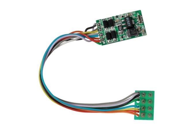
Typical Decoder
Hornby 4 function 8 pin decoder
Decoder installation into the loco’s will depend on several factors:-
a) Age of the loco. b) If the loco has Split Frame (Chassis) construction. c) Space available for the circuit board. d) Whether the loco is “DCC ready” i.e. the loco has a decoder 6, 8 or 21 pin NMRA DCC socket fitted by the manufactures.
Warning...Only ever convert a loco that's proven to run well on conventional DC before attempting to convert it to DCC. Converting a poor runner will result in equally or even worse running on a DCC system.
.gif)
“OO” gauge DCC Decoder Installation.
Unfortunately I can not make any comment on how to gain access to the insides of any particular loco, as the means of access varies considerably loco to loco. Please refer to the manufactures instruction leaflet or if not available then try their web site for maintenance access instructions.
How to install a decoder. Firstly, there are three types of locomotive available. As mentioned above at the beginning of this DCC page and to recap....
1) DCC Fitted or DCC On Board. A DCC decoder is factory fitted by the manufacturer of the loco.
2) DCC Ready. A DCC socket has been factory fitted, but there is no decoder. The loco is sold to run on dc power but can be readily converted to DCC. So the owner will need to remove the body and then remove the dc blanking plug and plug in a decoder of choice.
3) DC only. No DCC socket has been factory fitted and the loco is designed to run on dc track power. This later type is often found with older pre 2003/4 locos. Converting this type of loco to DCC is normally quite possible and is detailed further below.
Locos falling into groups 1 and 2 will normally have a NMRA plug/socket fitted. There are several types of sockets and these are:- 6 pin 'NEM651', 8 pin 'NEM652' and a 21pin MTC version often used especially where onboard sound is provided or can be added. The 21pin direct plug-in version is currently only found in 'OO'/'HO' or larger scales. It is planned that from around 2010 the 21 pin MTC connector will slowly be phased out and replaced by a new range of sockets called Next 18. The existing range of sockets and decoders will remain available along side the newer versions. Full details of all types of decoder socket connections can be found on the NMRA web site Link to NMRA Decoder Standards
Below are shown three of the current style of plug/sockets and their wiring for the 6, 8 and 21 pin versions. Normally the 6 pin NEM651 is used in 'N' gauge locos or smaller sized “OO”, while the larger 8 pin NEM652 and the 21MTC is used in 'OO'/'HO' and some larger scales.
.gif)
.gif)
.gif)
Below are a series of five pictures showing how a 21pin decoder was fitted into a Bachmann Class 55 Deltic locomotive. The loco is sold as 'DCC Ready'. i.e. Ready for immediate running on DC tracks and it has an 'On Board' factory fitted DCC socket which makes the loco ready for easy DCC conversion.
A Bachmann 21 pin decoder is to be fitted and the whole process took approximately 4 to 5 minutes. The longest time was the removal of the six body securing screws to allow the body to be parted from the chassis and then their refitting upon completion.


3 or 5 pole open framed motor is a little time consuming, but isn’t beyond the scope of this article and most people.
Having removed the loco’s body, view the chassis from above and on most older Hornby/Tri-ang loco's a ‘V’ shaped spring can be seen along the top of the motor, this retains both motor brushes under tension. One side has a slide on insulated sleeve. Locate and remove the push fit connector that’s located between the insulated sleeve and the actual motor brush curved upper part. This is normally a simple pull off fit and has a black wire soldered onto it which runs down to one side of the wheel set. Cut off the black wire where it’s soldered onto the connector. Discard the connector. The black wire will be used later.
Strip around 12-15mm of wire insulation (16/02 is ideal) and use the insulation to insulate the opposite side of the ‘V’ spring where it touches the brushes top or use a similar length of heat shrink tubing. This means now that both sides of the ‘V’ are insulated from the brushes. Next solder the Orange wire from the decoder onto one motor brushes top section and the Grey wire to the opposite brushes top. Be careful not to damage the insulation – slip a small piece of Paxolin or other heat resisting material between the brushes top and the insulated ‘V’ to prevent the insulation melting while the soldering iron is heating the brush/wire joint. When both are soldered visually check that the brushes carbon blocks are touching the motors commutator and there is no pull on the brushes from the attached wires.
The Ringfield Motor is quite easy to convert. Remove the body and note the style of motor and all its electrical connections.
Firstly, remove all the wires attached to the two motor's silver looking contact strips or their soldered connection . There may be two or more wires per connection do ensure any wires removed are always kept in their group. Cut off any crimped 'push on' connectors from the wire ends. The two silver coloured strips hold the motor brushes in place. IMPORTANT - THIS NEXT TEST MUST BE CARRIED OUT BEFORE PROCEEDING FURTHER..... Test the two silver brush strip with a multi-meter set to its OHMs range or use a simple battery operated buzzer, battery and two test leads. Test the left-hand strip to all wheels and the metal chassis. Then do the same with the right hand strip. No reading or buzz etc should be observed with any test. If there is a reading or the buzzer operates refer to 'Ringfield-2' below. Assuming all is correct, then solder the Grey and Orange decoder wires onto the silver strips - often the factory soldered capacitor gives a nice soldering point to solder these wires onto. Now cut two 10-12mm lengths of Heat shrink tubing and slip one onto each of the two set of wires removed from the silver strips earlier. Strip a small amount of insulation off these wires if not already stripped, and then solder the Red decoder wire to one and the Black decoder wire to the other. Slip the heat shrink tubing over the soldered joints ensuring all the stripped and soldered area is covered, then apply a little heat to shrink the tubing down to make a nice solid and insulated joint. Place the motor assembly (Tender chassis) and the loco as well, which must be coupled to the tender unit to provided at least the one electrical path via the locos wheels, onto the Programming track and select 'Programme'. You should now be able to read back the manufactures address setting if your system allows this An new decoder should show 3. As normally they are factory preset set to 3. If all is ok, then programme to a new address number as needed. Once programming is completed test the chassis & loco body on normal DCC operation. In the event of the loco running in the opposite direction to the controllers setting (e.g. reverse when forward selected) unsolder the two wires on the Silver strips (Orange and Grey) and reverse them. Or alter the value in CV28 to correct this.
.jpg "Ringfield Motor Insualted type")
 (2017_01_23 23_11_49 UTC).jpg)
.jpg "Completed decoder installation using an in line connector")
.jpg "The 'Newer' Ringfiled motor fitted witha Bachmann decoder")
IMPORTANT....... Check after reassembly of the brush strip and regardless of whichever of the above methods are used, that there is no connection between the two brush strips and the chassis. Do this with a multimeter set onto its OHMS range or use a battery powered buzzer continuity tester. Carry this out so as you test that the left-hand and then the right-hand brush strips are actually fully insulated from the chassis. Place one lead onto the chassis and the other onto the left-hand strip. No reading (or a buzz, if a buzzer is used) should be observed. Then leave the chassis test wire in place and move the other test wire to the right-hand brush strip. Again no reading or buzz should be present.
Failure to prove there is no electrical connection to the metal chassis on either strips will result in the decoder terminally failing as soon as DCC power is applied!
If all ok, then there is now the need to provide a connection onto the chassis for one of the decoders track pickup wires (The red wire). This will mean finding a suitable place for the red wire to connect onto. This, if you're lucky, can be a factory fitted wiring tab on the chassis. If no suitable tab exists then I found I had to use a small self tapping screw which was fitted at a suitable location. Do this by drilling a small hole into the chassis and then driving in the small self tapping screw, before fully tightening down the screw, loop the red wires stripped end under the screw head in the direction of tightening and then drive the screw down fully. Solder the Black decoders wire to the existing wire that was removed from the right-hand brush strip. Cover this soldered joint with insulation tape or use heat shrink tubing. Solder the Orange and Grey wires to the brush contact strips.
Ensure the chosen location for the decoder will be clear of the tender body and this place where its being fitted has a layer of PVC insulation tape over any metal chassis. Use a self adhesive double sided sticky pad to hold the decoder in place. Cut off or roll up all the remaining wires (These aren’t normally used on Steam outline models normally) and tidy the four other wires into a neat bunch ensuring they wont foul the tender top or any motor drive gearing etc.
If the loco runs in the opposite direction to the controller setting, reverse the two wires (Orange & Grey) on the brush strips.
All this sounds quite daunting, but really its fairly straight forward!
 (2017_01_23 23_11_49 UTC).jpg)
Class J94 0-6-0 Tank Loco This Hornby model is quite a simple conversion. I had a spare Bachmann one function decoder so this is what's being installed. Having removed the two underside screws located either side of the cab and then the chimney screw and chimney, place all screws removed carefully to one side. Unscrew the two screws retaining the large weight block and lift off weight. Remove the four screws securing the front and rear motor retaining plates. Lift motor and attached wires clear of body. Unsolder the top and bottom motor wires from their motor connection tags. Cut off at the edge of the circuit board on the decoder the two unused lighting wires (Yellow and Blue) If you're using a three function or more decoder then there will be other wires to cut off too. You should only have the Red, Black. Grey & Orange wires left. Strip a couple of millimetres of insulation off from each wires end and twist up their ends and tin with solder. Slip a length of heat shrink tubing onto the wire going to the motors top connection (Orange in my case but may be the grey wire) and solder the orange and grey wires to the motor tags. NOTE: As the loco chassis is all plastic on this model no sleeving is needed for the bottom tag/wire joint. Slide the tubing down until its over the tag and any bare wire and then apply the tip of the soldering iron carefully to shrink the tubing over the joint. Slip a piece of heat shrink tubing over the red and black decoder wires and solder these wires to the wires removed originally from the motor. Red decoder wire to the right-hand side pick-up wire and the black decoder wire to the left-hand pick-up wire. Slip the tubing over each joint and shrink down. Replace the front and rear motor retaining plates keeping the four decoder wires on top of the rear (cab end) plate. Visually check no wires are foul of any moving parts. Now test the decoder on the Programming track. Now run the four decoder wires into the footplate area via the existing central notch in the footplate floor. I held my wires in place with a spot of Superglue. If all is good then with the aid of a small flat file open up the notch in the bodywork where the firebox door is. A small notch already exists, but this notch needs to be made deeper to allow the four wires to pass into the cab. Do this filing carefully and check frequently to see if the cab fits correctly onto the footplate. Once correct, refit the body with the two screws and the chimney screw. Carefully work the decoder into position against the rear cabs wall. using a spot of superglue hold the decoder in place. Tidy the wiring in the cab and retest the loco on the track. If its wished, the decoder and the wiring can be given a covering of mat black paint to help hide it. Add a driver and fireman and jobs done!
,
 (2017_01_23 23_11_49 UTC).jpg)
 (2017_01_23 23_11_49 UTC).jpg)
 (2017_01_23 23_11_49 UTC).jpg)
 (2017_01_23 23_11_49 UTC).jpg)
 (2017_01_23 23_11_49 UTC).jpg)
 (2017_01_23 23_11_49 UTC).jpg)
 (2017_01_23 23_11_49 UTC).jpg)
 (2017_01_23 23_11_49 UTC).jpg)
 (2017_01_23 23_11_49 UTC).jpg)
Bachmann split chassis locos are a little more difficult to convert but here's the basics....
Firstly, I only recommend the use of a quality decoder such as Lenz , Zimo or TCS range for these conversions as they have excellent fine tuning characteristics and seem to match the Bachmann older can motors well. Other decoders may well be equal or better, but I happen to like these. The final choice must of course be the end users.
Secondly, some time should be spent on deciding the exact the location of the decoder in the loco. Space inside most Bachmann steam outline locos is at a premium! Cutting away some of the locos chassis block isn’t one of my favourite options! Though it can be done with care.
Generically to fit a decoder, you have to strip the loco right down and open the chassis up into two halves, place all the items removed in a container until needed for reassembly. Now remove the motor and worm cog assembly and solder onto the motor tags two fine insulated wires. Place a small length of heat shrinkable tubing over the tag and soldered wire and shrink down so as no exposed metal of the tag or any uninsulated wire is visible.
Now drill two 2mm dia. holes in a place somewhere on the outside of each chassis half and slowly screw in two small (e.g. 2.2 x 6.5mm) self tapping screws. Screwing in half a turn, then undo a quarter turn, continuing on like this until they are driven fully home. You have to carefully choose a place on the chassis so as the small screw heads won’t foul the bodywork when it's replaced. Often on top or at the end of the chassis block will have a clearance space, but do carefully check. Ensure all drilling swarf is removed. Having screwed the self tapping screws right down now unscrew them a couple of turns. Before refitting the motor back into the chassis, place a sliver of insulating tape onto each half of the chassis covering the area where the motors wiring tabs sit.
 (2017_01_23 23_11_49 UTC).jpg)
 (2017_01_23 23_11_49 UTC).jpg)
 (2017_01_23 23_11_49 UTC).jpg)
 (2017_01_23 23_11_49 UTC).jpg)
 (2017_01_23 23_11_49 UTC).jpg)
 (2017_01_23 23_11_49 UTC).jpg)
 (2017_01_23 23_11_49 UTC).jpg)
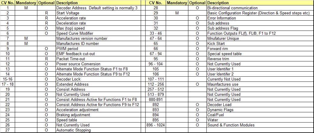
CV settings... Configuration Variables (CV) control the way the decoder controls various functions within the loco or accessory. They are 'memory slots' where a specific piece of information is stored for a specific operation. CVs settings are retained even when the console is turned off or in the case of a loco decoder, when a loco is removed from the rails etc. Most CVs can be altered, except for a couple which hold manufactures data about the actual decoder and its software version (CVs 7 and 8). But most are adjustable and by fine tuning a particular CV from its default setting, better or finer control over that operation can be achieved. The most basic CV that virtually everyone using DCC will adjust is CV1. This sets the mobile decoders address number (default setting is always 03). Other CVs such as acceleration and deceleration rates (via CVs 3 & 4), the maximum fastest speed permitted (Top Speed via CV5) and lighting control CVs i.e. those that control the way the locos lights operate etc are then next group often to be fine tuned by the user. Think of CVs as a bit like being a radio with pre set tuned radio stations buttons. So the position 1 button on the radio when pressed gives you a specific radio station, but by fine tuning button 1 you can then make the radio receive that radio station better or worse. Similarly, CVs are turned, but they only alter the function or operation they are designed for. So for example; you can alter CV3 value and make the loco accelerate away more slowly from stop, by increasing the number (called the 'value') entered into CV3 when its being set. But you can't make CV3 become the Top speed CV which is CV5.
So to recap, on a loco by adjusting individual CVs that locos performance can be enhanced. Note; not all CVs are available in all decoders and some consoles may not offer the ability to configure them individually. Reference to the DCC system manufactures manual will show which CVs the console unit allows adjustment of and how this is carried out.
The list below gives the general overview of those CVs mainly available. Note; that the NMRA also specify to the decoder manufacturer that some CVs should always be available i.e. mandatory (M) while some others are either optional (O) or recommended (R) . For a more detailed list visit the NMRA site and see table 1 NMRA Standards pdf Also refer to the decoder manufactures manual/instruction sheet.
Decoder controlled lighting or other operations, such as powering smoke units, firebox flicker or cab lights etc are easily obtained by using the Function outputs available on most decoders. Note most decoders Function outputs are limited in the current they can supply and this must be taken into account when connecting them to devices (Typically, decoders can supply 100milliamps per function output, but some makes can control and supply higher currents, so always refer to the manufactures leaflet). Some loco decoders will offer one or two function outputs, while others and perhaps the main stream types, provide three or four separately switched function outputs. There are some decoders that can provide six separate function outputs. Each output is controlled via a 'F' key operation on the console. A Single function decoders function via its White wire is often controlled by either the F0 or F1 console keys. Operating say the F0 key turns on the output and operating that key again turns off the output. On three function decoders it is normal to find them as supplied, with the White and Yellow output wires being switched on/off by the F0 key and this provides automatic directional controlled front and rear lighting and the Green wires function is operated by the F1 key. On a four function decoder F0 still controls directional lighting via the White and Yellow wires, F1 controls the green wires function on/off and the Violet wire is now controlled by the F2 key, again turning on/off that function with each 'F' key operation.
In all cases, and regardless of the number of Functions, the Blue wire is the Positive supply and is a common connection to all devices. This is not switched on / off. It is the returns, via the white, yellow, blue, violet etc wires that are actually switched on/off within the decoder.
You can use a 'Function only' decoder or a more conventional 'Motor and Function' decoder for lighting, and then not use the two motor connections. However many motor and function decoders will require a resistance placed across the two motor wires to allow Programming and CV read back to occur. Simply connect a 100R (100 OHM) resistor across the Grey and Orange wires and this will act a as 'dummy motor load' and allow the decoder to be programmed and read back as normal.
A lot of decoders now sold allow the user to reconfigure their Function outputs, call mapping, so as for example F1 controls the front light, F2 Rear lights. F3 and F4 can be used of additional lighting or other device operations as needed. This is carried out by altering the CV settings within the decoder. Refer to the decoder manufactures leaflet for details on which CVs allows which function outputs to be reconfigured.
Note: The reason for reconfiguring is often while Function F0 is normally a decoders controlled automatic directional lighting output and used for front / rear lighting, the rear lights on a loco will remain on when the loco is pulling a train. Or when the loco is stabled the red rear lights may be required to be left on but the front headlamps or front white marker lights are also on too, neither of which is really prototypical. So reconfiguring is at times an option chosen to overcome this.
Several combinations of decoder wiring going off to the lights typically, but they can feed other devices, can be carried out. As stated above, often automatic reversing of the front and rear (white and red) lamps occurs when the locos direction is changed. A two or more function decoder will normally automatically switch the outputs over on the White and Yellow wires. (F0 operation to turn this feature on)
The basic configuration is shown below for a single function decoder.
.gif)
The next example shows a two function decoder
.gif)
In the wiring example below a three function decoder is used to feed front and rear (White and Red) LEDs and the third function - Green wire is used to illuminate the drivers cab or perhaps provide coach lighting where a multiple unit is used and the coaches seating area is in the same coach as the motor and decoder.
.gif)
The fourth example drawing shows a four function decoder being used two give separate controls to the front and rear lighting. So for example the rear red lights of the loco can be turned off when its pulling a train.
.gif)
Smoke Units in locos on DCC are possible. You can obtain low current rated smoke units that are able to be directly function feed, but the rating of the smoke unit in milliamps must be less than the decoders single function rating (also in milliamps). The other alternative and one I would recommend using, is a small sub miniature 12 volt relay to switch the actual smoke unit On/Off where the realys coil power requirement is lower than the decoders function output rating. Power for the smoke unit is derived from the DCC power but by passing the power via the contact of a relay will ensure there is no possible overloading of any Function output of a decoder. Many decoder function outputs are only rated at 100 milliamp while a lot of smoke units require 120 to 200 milliamp to operate. A relay will allow operation without overloading the function output. Operation is... Function 'F1' (usually the green decoder wire) turned On and this allows the relay to operate and close its contact - Comm to N/O. DCC track voltage is then allowed to pass to the smoke unit. Once smoke operating is ended the 'F1' key is operated and the relay releases opening contacts Comm - N/O.
It is wired as per the drawing below..…
.gif)
As stated above, some decoders have Function outputs able to directly drive a smoke unit. Also some smoke units are sold as being low current, typically below 100 milliamp (0.1A). Always check the current draw of a smoke unit and then cross reference that current to the rating of the function output of the decoder. Some decoders and DCC systems allow the pairing of two functions by re mapping the decoders functions to work as one via one F button, so two function outputs are paralleled together to from one function output and are then able to provide double the current of the one function output.


Where to now?


All items appearing on this or any page of this web site are the intellectual property and © copyright of Brian Lambert. Unless otherwise stated.
You MUST NOT make available by placing them in any public domain area or in printed format any copies of Text, Image, Drawing or Video shown on this web site.
No item as listed above should be used, copied, linked to or forwarded by any third party without firstly obtaining the written permission of the web site owner - Brian Lambert.
You may freely and for personal use only, copy or print any areas.
You may refer to this web sites page electronic address detail (URL) in any other media - printed or electronic. Any such referenced URL should commence.... https://www.Brian-lambert.co.uk/
Brian Lambert accepts no responsibility for any item appearing on this or any other page of this web site.
All items are given in good faith.
By visiting this web site you agree to accept and abide by all the condition shown above.
NORMAL & STALL CURRENT TEST You should know the normal full load and stall current of the loco’s motor, as this will determine the choice of decoder to be installed. To find out the normal running and stall currents you will require a normal dc train controller, a length of track (Not connected to any railway) and a suitable dc reading amp meter (digital or analogue multimeter with a dc ampere range of at least 1.5amps (for “00” locos) DO NOT USE THE DCC ENABLED TRACK FOR THIS TESTING.
Connect one wire from the conventional controller to one of the tracks rails. Connect the other controller’s terminal to one side of a dc reading amp meter. Connect the opposite terminal of the amp meter to the remaining track rail. You now have a amp meter connected in series circuit! Place loco on the test track and gently stop the loco to prevent it from moving forwards or backwards. i.e. Place a finger in front or behind the chassis to allow the wheels to slip, but prevent the loco moving, then turn up the controller to full power. The meter should now be reading the normal full load motor current flow. Now carefully stop the locos wheels from turning, or in other words stall the motor. Note the current being drawn on the meter WARNING - DO NOT ALLOW THIS STALL CONDITION TO LAST FOR MORE THAN 3 or 4 SECONDS or the motor may well burn out! Once you have obtained both the normal and the stall currents, select a decoder that will handle that noted stall current. Choose a decoder that's rated above the normal running current and that can also handle the stall current. Most decoders will be rated between 0.5 and 1.5 amps dc continuous for “00” and for “N” gauge a rating of 0.5 to 1.0 amp.
Page Quick links
Ringfield-2 Conversion of the second type of Ringfield motor to DCC is possible, but does require more work. The important thing is to isolate the two motor brush retaining clips so as they cannot make contact (as supplied) with the chassis or wheels. There are two main types of motor supplied, which ever type you have you will need to determine there is no connection once all wires are removed from each strip to all wheels. Failure to carry out this work and test will result in immediate decoder failure!!!
Style 1 has a small tag on the left hand brush strip trapped under a 'U' shaped metal bracket. The metal 'U' shaped bracket and the sliver coloured tag are making electrical contact to the chassis. As too is the hidden small 'Pip' of metal sticking out from the chassis and touches the rear of the silver tag behind the 'U' shaped bracket. These connections MUST be removed. The tag MUST be insulated so as its front and rear cannot touch the 'U' shaped bracket or the 'Pip' behind the tag. You can use insulting tape or better still is to use heat shrink tubing placed over and shrunk down onto the whole of the strips tag.
In the above:- left shows a Hornby A4 tender drive Ringfield motor as supplied for normal DC working. Second left shows the capacitor and feed wires removed as this motor didn't run very well with the capacitor fitted. Third shows the completed DCC installation ready for the decoder to be fitted onto its plug. (The unused lighting wires are either cut off short or tucked away neatly when the tender top is refitted). Right shows the newer Ringfield motor with a Bachmann decoder being used. Note: Here the capacitor is remaining and the decoders motor wires are soldered onto the capacitors leads where formerly the three wires per pick up where soldered. These wire have then been soldered together as a group and one of the decoders input wires (Red & Black) have been solder to that group then covered over by heat shrink tubing.
Above: Left Photo shows a Hornby Ringfield motor. This is perhaps the easiest to convert of all three styles. Both silver coloured motor brush strips are insulated from the chassis. Once the wires are removed it is then ready for conversion. Right Photo shows what I call in the above text, the 'Style 2' Hornby Ringfield motor, where the left-hand brush strip is in direct connection to the metal chassis via the strips retaining screw.


Above shows the style 2 Ringfield and in the last image where the problem of the left hand brush strips connection is to the metal chassis. Its vital to remove this connection.
Turn the point over and using a Jewellers Piercing saw or an electric slitting disc cut right through both closure rails on the frog side from where the solder wires are located and in the next convenient open space between sleepers. (Shown in green in the photo) The cut gap can be filled if wished by inserting a small piece of Plastikard or similar plastic material into the gap and holding it in place with a drop or two of Superglue. Once the glue has set, cut off all surplus Plastikard etc with a sharp craft knife ensuring there is no card above or extending either side of the rail, which could derail a trains wheel set Give the top and inner faces of the two joints and rails a couple of strokes of a flat needle file to smooth the area completely.
Non DCC Ready loco conversions.
If the loco isn’t DCC ready it must be determined whether or not the motor and its brushes are in contact with any metal of the chassis and hence to one side of the rail via the wheels of the loco. If it is, and most non DCC ready are, it can be determined by using a multimeter switched to ohms and looking for a reading between either side of the frame/chassis and both brush connections (or motor feed terminals if the brushes aren’t accessible), if a reading is obtained then the motor brushes or motor terminals must be insulated from the chassis. I can’t describe how to undertake this in detail, as every loco is of course different, but this action is essential to undertake. I have described below the basic conversion techniques I have found necessary on many 'generic' loco's and also I am showing how to convert some of my existing locos too.
Where the motor is insulated, then the existing wires from the wheels to the motor terminals have to be unsoldered at the motor end – Make a note of which colour wire goes to which side of the loco. Once these two wires are removed connect them to the red and black decoder wires by twisting and soldering the ends together. Note the red wire connects to the right-hand side looking forward and black to the left-hand side. Before soldering cut a small length of heat shrink tubing to cover the final joint and slide this onto one end of the wires, then twist and solder. Slip the heat shrink tubing over the cooled soldered joint and gently warm the tubing until it’s shrunk down and has made a nice insulated cover over the joint. (Use the soldering irons tip if you don’t have a micro warm air tool). Now connect the Orange wire to the motor terminal where the right-hand original wire was. Then do the same with the Grey wire connecting to where the left hand side wire came off
Several style of non insulated motors are to be found – 3 or 5 pole open frame, Ringfield and Can styles. Of all these, the Ringfield is probably the easiest to convert and is often found in older Hornby and Lima tender drive steam locos and many Hornby and Lima diesel outline locos and DMUs.
When converting an older loco I would recommend that only the best quality of decoder is used. i.e. Lenz Standard+ or Silver or something from the Zimo range be used. This will ensure that older style motors perform to their very best.
Now slip a short length of heat shrinkable tubing over the black wire (removed earlier from the insulated side of the brush) and then solder the decoders Black wire to this. When cool, slip the tubing over the joint and apply a little heat to shrink the tube to form a good insulated joint. Finally connect the Red wire to the central screw that holds the ‘V’ wire in place by undoing the screw a little, stripping approx. 10mm of insulation from the red wire and twisting up the strands to make a solid wire then wrap this stripped end clockwise around the loosened screw. Tighten the screw to grip both the wire and the ‘V’ spring.
Place the loco onto the Programming track and check that the decoder can be read , normally its factory preset set to 3. If all is ok then programme as needed.
Once programming is completed test the loco on normal DCC operation. In the event of the loco running in the opposite direction to the controllers setting (e.g. reverse when forward selected) unsolder the two wires on the brushes (Orange and Grey) and reverse them.
When reassembling the loco body ensure the area chosen for the decoder’s final position is well insulated. Remember that the chassis is live and will cause a short circuit and destroy the decoder it if it’s not suitably insulated. This can be carried out by applying insulating tape to the area of the decoder’s location and then holding the decoder in place with double sided adhesive pads. Make sure decoders wires are taped clear of any moving parts too.
When reassembling the loco body ensure the area chosen for the decoder’s final position is well insulated. Remember that the chassis is live and will cause a short circuit to the decoders printed circuit board and destroy it if it’s not suitably insulated. This can be carried out by applying insulating tape to the area of the decoders location and then holding the decoder in place with double sided adhesive pads. Make sure all the decoder’s wires are taped clear of any moving parts.
Style 2 has the left-hand strips retaining screw is touching the silver brush strip and screwed into the metal chassis. This screw should either be removed and replaced with a suitable nylon screw if one is available (I understand Peters Spares sell them as part number PS13 in a pack of 10. I have also been advised that the Kadee 2-56 x 1/2" nylon screw is ok too). If you're not able to obtain a nylon screw, then there are two alternative methods....
1) Remove left-hand screw and fit a short length of suitable sized heat shrink tubing over the original screws head and a short way down its body. Shrink down the tubing and carefully refit the screw ensuring none of the tubing is damaged as the screw is driven gently home.
2) The left-hand contact strips screw will need a short piece of thin tube and a Plastikard washer made up for the front side to fit under the screw head. This sleeving together with the Plastikard washer will then prevent the screw from touching any part of the brush strip. Or use a Transistor Top Hat insulator if one is available. Both may result in the need to open up the hole/slot in the brush strip a little to accommodate the new wider fixing.
Some basic DCC systems will state “Simple two wire control” while this perhaps is true it isn’t often reality. All electrical power needs to get from its source to the motor or decoder or wherever it is needed as easily as possible. Electricity is basically lazy and if an obstacle is placed in its path it won’t try very hard to get over the problem, it just lays back and rolls over! This is often due to, and is called, a high resistance joint. So think of it as.... Power comes from the control unit onto the rails, from here it has to pass through numerous metal rail joiners (fishplates) to get from one track section to the next track section etc. Eventually it arrives at the wheels of the loco, then in most cases via wiper contacts touching on those wheels and then onto the decoder. Now, how many places of possible high resistance has the power passed through? Probably 30 or 40 plus! I’ll list a few of them - Rail connecting clip to rails, two metal rail joiners per track section, point blades to stock rails, rails to loco wheels, wheel wiping contacts to the final connection to the decoder. Now each one of these ‘resistance places’ is a possible cause for trouble!
The main culprits are – Dirty rails, dirty wheels, dirty wheel wiping contacts and of course the loose and or dirty metal rail joiners or the rail ends themselves. Quite a few items! That’s without the possibility of the rail power clip being a poor connection!
How do you avoid all these? Well, by keeping the rails clean by using a track cleaning block and a loco’s wheels clean with the aid of a wheel cleaning set (Both available from model shops and manufactured by Peco for example) and the use of a fibre pencil on non powered wheels. Cleaning of the rails only needs to be undertaken once every week or so and that’s where a layout is used regularly. However, if the layout is put away and not used for several weeks etc then the rails should be cleaned before use as they will have tarnished.
Compatibility, one advantage is that virtually all the DCC manufactures produce their products to be compatible and to a set of standards written by the NMRA National Model Railroad Association which makes mixing and matching possible with differing makes of control systems and differing makes of decoder. Whether or not the decoders are factory fitted inside the locos or installed by the locos owner. e.g. A Hornby loco and decoder can be operated by Bachmann DCC console or a Hornby loco can be fitted with a Bachmann decoder and be operated by a Lenz console. There are many other combinations possible of course.
**If you're using the solid conductor mains cable for the bus wires then carefully strip out the two insulated conductors from the cables outer sheathing. Discard the outer sheath and use the two insulated conductors - Red & Black or Brown & Blue. The bare (former earth) wire removed from the stripped cable can be saved and cut up for use as rail droppers perhaps? or as I have done, run this also around the layout and use it as a Common Return bus for everything else that’s not directly DCC controlled. e.g. Street lighting, building lights, colour light signal aspects etc. Do not use a common return wire for DCC operations though!
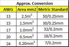
Below is a chart showing the approximate conversion sizes of some of the more commonly used wire sizes found in DCC wiring
Carefully reassemble the chassis, ensuring the plastic spacing washers are all in place over the plastic tubes that protrude through the inside of one chassis half, it is into these tubes that finally the chassis securing screws will locate and pull up the two chassis halves. Checking all the time nothing is being trapped or causing binding. Then test with the aid of a buzzer or multimeter set on its ohms range that there is no connection between the two chassis halves, nor is there any contact from either chassis half to either of the two wires previously attached to the motors tags. If all testing is ok, connect the two decoder wires to the self tapping screws by looping the stripped end of the decoders red wire clockwise under the right-hand self tapping screws head and drive the screw down until the wire is trapped firmly against the chassis. Then do the same with the black decoder wire under the left-hand screw. Finally cut to the length required, strip and joint the two wires coming from the motor to the Orange and Grey decoder wires and then solder them, covering the soldered joints by using a short length of heat shrinkable tubing previously placed onto each wire before twisting and soldering the joint.
Test the decoder by using the DCC Programming track. If all is well then whenever possible secure the decoder to the chassis. The chassis being previously covered with some PVC insulating tape in the decoder’s fixing area, or alternatively locate the decoder somewhere inside the locos plastic body. Use a double sided sticky pad to hold the decoder in place if possible. Carefully replace the body checking all the time no wires are being trapped or are going to foul any moving parts
In one of my loco’s there just wasn’t anywhere to locate even the smallest of decoders in the locos body (an old J39), so I opted here to place the decoder in the locos tender and run four fine wires between loco and tender. This means the tender is permanently coupled to the loco and the four wires where they pass between loco and tender were painted matt black and become virtually invisible.
The most simplest layout can be wired for DCC by using two wires from the consoles output terminals to the first pair of tracks then linking onto the next pair of tracks and so on. Ensuring rail polarity is maintained throughout the wiring process. i.e. outer rails all connected together and all inner rails together. Where points are feeding a siding there is normally the need to install a single wire onto the rail that leads away from the frog to ensure the siding remains live all the time, regardless of the points position. Below can be seen the very simple and basic wiring needed for a twin tracked single siding layout. There is only one wire feeding the siding track, as the upper siding rail already has a feed onto it from the curved rail of the point and then from the loops track feed. Note; this example is not drawn as any specific layout or deemed as a layout to construct.
The diagram below shows the set up for a console without a Programming output and how the track at the end of the siding is wired to a DPDT switch. When the 'Programming' position on the switch is selected the rest of the railway is disconnected and only the end of the siding is DCC powered, thereby ensuring no locos on the main tracks are accidentally reprogrammed. You cannot drive a loco into or out of this programming section of track without operating the switch to the 'Programme track' position and thereby feed the programming sidings rails. Example... The loco to be reprogrammed approaches the programming siding area with the selection switch still in the 'Normal' position. Eventually and once all the locos pick-up wheels have passed over the two IRJs the loco will stop. Flip the switch to 'Programming' and drive the loco in further as needed. Carry put the programming work as required safe in the knowledge that all the other locos on the main lines cannot be accidentally programmed, as the whole of the main layout has been electrically disconnected. Once the programming work has been completed drive the loco out of the siding area and eventually the loco will stop once its passes over the two IRJs. Flip the programming switch back to the 'Normal' position and then drive the loco away as normal as the rest of the layout is again fully powered, except the programming section of track which is now electrically dead again.
The easiest means of providing a programming section of track regardless of the consoles outputs is to use the end of a siding. Shown below are two methods of how to wire this 'end of siding' track section, depending on whether or not the console has the programming output. In all cases a pair of insulated rail joiners are fitted in the two rails at least the longest loco or multiple units length from the buffer stops and add about a further 50mm to ensure the item fits inside the insulated area easily. The siding end depending upon the switches position, can become a totally insulated section for programming from the rest of the railway.
From the bus, there will be usually many connections between it and the running rails to ensure reliable power and data transfer into the rails and hence onto the loco’s wheels and the decoders. I advocate a DCC bus being made of at least 1.5mm2 or 32/0.2mm equipment wire and better still on medium sized layouts using 2.5mm2 solid wire or 50/0.25mm flexible, solid wire can be taken from domestic wiring cables (See ** below). Larger layouts may need even a bigger gauge of bus wire. Flexible wire for the bus can be used if preferred, and may be especially useful on portable layouts! If using a flexible wire for the bus then choose a conductor size of at last 32/0.2mm while 50/02.5mm can be used on larger layouts. Note the size of the bus conductors has little bearing on their current carrying capacity, though they of course it must exceed the rating of the DCC system and power supply. Using what may seem like excessively large conductors is not only because of the power supplies output current, but also because of the volt drop encountered in the copper wires and the need to ensure reliable data transfer between console and the furthest point out on the bus is maintained. On very long bus wire runs it may be necessary to install a simple resistor and capacitor terminator filter across the bus pair of wires at both termination ends, as this will ensure reliable data transfer along the bus. Details of the terminator filter circuit are given later.
All connections onto the bus should ideally be soldered. Simply remove a small portion of the bus cable insulation (about 20mm is ample) with wire strippers or a craft knife and and strip approx 10mm from the end of the dropper feed wire, then wrap the track feed wire around the bared copper bus wire. Apply a pre tinned hot soldering iron to the two wires, wait a few seconds for the joint to heat and apply a little cored solder onto the joint (Not the iron) until solder is seen to flow into the wires. Remove iron and leave joint for some 10 or more seconds to cool, then cut off any surplus dropper wire end. If you wish, a small amount of insulating tape can be wrapped around the joint to prevent it touching any other part of the bus.
LOCOs:
Locos. There are basically three types of locos supplied -
DC Only (Not DCC Ready) = Older models which do not have any DCC decoder fittings and if converted require the decoder to be hard wired into the pick up and motor circuit.
DCC Ready = A decoder is not fitted, but they have a removable connection called a 'Blanking plug' which allows the loco to operate on DC and removing it then inserting the chosen DCC decoder allows the loco to operate on DCC (and usual DC too).
DCC Fitted or (DCC On Board) = This loco has a DCC decoder fitted and will operate on DCC power and should also operate on DC rail power too.
Never place a older unfitted loco or a DCC Ready loco that has not had a decoder fitted onto DCC powered rails. It will not operate and will buzz or Hum which is the motors armature moving a tiny amount each way at the frequency of the DCC - around 8KHz. The motors coils will burn out if the loco is left on the DCC powered rails without a decoder! Some DCC systems allow one DC loco to be operated on by the DCC system using address number 0 (zero) This is not a recommended practice and should really be avoided.
Another decoder found is the Accessory Decoder. This is for use with stationary accessories such as point motors or Signals etc and interfaces between the DCC system and the accessory. You cannot operate any accessories directly from the DCC system, so an accessory decoder is required. Some are built in while others are sold separately.
The conversion process above show an old Bachmann J72 tank loco which has been proven to run well on dc. In Photo 1 the body has been removed prior to any conversion work to try and find a suitable place for the Lenz Standard decoder. Photo 2 shows the final location of the decoder, inside the cab roof, this is due to there being no space whatsoever in the main body! Photo 3 shows the two halves of the chassis. Photo 4 shows the self tapping chassis connection screws fitted. Photo 5 shows the decoder wires connected to the motor and terminals covered with heat shrinkable tubing. Photo 6 shows the loco being tested and set up on the rolling road rather than on a programming track (The rolling road is connected to the programming track by a short lead and croc clips). While the final Photo 7 shows the body refitted and the loco being fully set up and tested on the rolling road. before being used on the main line tracks. - Spot the decoder or its wiring!
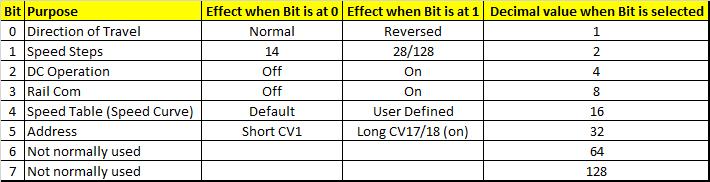
Of all the CVs, CV29 is the one that always seems to give the most user problems. It is also the CV that can cause most problems!
It seems to be the DCC fraternity always refer to CV29 'Bits' rather than decimal values which cause many non Binary people a headache!
To help, here is simple table of what each Bit in CV29 does and its decimal value.
Note: Some consoles will automatically select the values in CV29 on certain features for you.
Add together the decimal values of all the features required and then enter this total value into CV29.
Example... Direction of travel reversed (1), Speed steps at 28/128 (2), DC operation On (4). Entered value in CV29 would be therefore be '7'.
I regret that due to the large amount of text and drawings these Electrical Pages hold they are not available via a mobile (Cell) phone. Please use a Tablet or PC for viewing them.