www.brian-lambert.co.uk

Electrical Page 3
Points - Part 2 & more Electrical.
Fixing a Peco PL10 motor directly to the point. On "OO"/"HO" points bend the central two fixing lugs over to an 'L' shape ensuring the dive pin is not fowled by these bent lugs, then insert the drive pin into the tie bars hole and carefully push the four lugs on the ends of the metal frame into the pre made slots of the points sleepers. For 'N' gauge, bend over one outer ends set of lugs and use the central and opposite ends outer lugs for fixing to the point. In all cases check the drive pin can move the point blades over and back by using your finger underneath the motor on the free end of the drive pin with the motor held securely in place. There should be no binding anywhere in the travel. Once satisfied all is correct, carefully twist slightly the protruding tabs above sleeper to retain the motor securely in place. Again recheck the drive pin is able to move the tie bar freely. Now you will need to cut out a rectangle of baseboard to allow the motor and its wiring to sit into. A hole approx 40 x 25mm is required. Cut this out by marking in pencil the rectangle shape and then drill four 6mm dia holes in each of the corners. Use a pad saw or electric jig saw to cut out the four sides between the pre drilled holes. Once the point, motor and its wiring is installed, you can cover over the hole with some very thin card or paper etc. Cut the card or whatever is used, larger than the hole and then cut it in half along its longest side. Mark centrally a small slot of approx 10mm length and 2 mm width on each half and directly opposite each other. Then cut out the rectangle in each piece. Mark and cut outer slots to allow the card to slide past the motors upright fixing brackets on each side. Then slide each half under the point so as the drive pin sits inside the cut out rectangle. Check the point moves freely both ways and if required fix the card to the baseboard with some PVA or UHU type glue. The card then acts as a cover for the large hole the motor sits in.
An example of the simple 'cover plate' needed when a motor is sunk into the baseboard is shown for "OO"/"HO" points below.
Fixing Peco PL10E Motors (Below baseboard). This can also apply to the Hornby R8014 motor, but ensure the drive pin is long enough to reach the points tie bar after passing through the baseboards thickness.
Fixing is easily carried out on the underside of the baseboard by using two suitable length and gauge wood screws and two brass style screw cups of the same screw gauge. e.g. use No 6 x 1/2" (3.5 x 15mm) screws. Or two round head woodscrews and flat washers used in place of the screw cups, though I recommend the screw cup method for easy of use and any fine positioning adjustments needed. Firstly, mark in pencil where the tie bar exactly lies, mark centrally to the left and right sides of the bar and also centrally either side of the operating hole in the bar in line with the track or if possible mark through the hole in the tie bar by holding the points blades centrally, then remove the point. Join the marks to form a cross, where the cross intersects or where the central mark is drill a 9mm diameter hole, this is the position where the drive pin needs to enter the tie bar from below when the motor is fitted. Alternatively, drill two 4.5mm dia. holes side by side and elongate them together to form a slot approx. 9mm x 4.5mm. On the motor, bend the outer fixing tabs down to form an outward curved "L" shape and bend the inner pair to allow flush fixing - ensure they do not fowl the drive pins movement and then install the motor carefully from underneath. Ensure the drive pin has located into the hole in the tie bar. Hold the motor firmly in place and with the motors drive pin to one side (The same side as the points are laying). Now move the pin over to the opposite position by hand from underneath by using the pin that protrudes from the underside of the motor, ensure the points move over correctly both ways, if not adjust the motors position as needed. If all is ok then mark centrally both fixing centres with the aid of a bradawl or awl. Slip a brass type screw cup onto a suitable wood screw and drive the screw into place to hold the motor firmly to the underside of the baseboard. Recheck that the motor still moves the points both ways, if ok then repeat for the opposite tab. Note the cups outer edges should encompass the motor lugs and by clamping the lug holds the motor secure. Recheck that the motor still moves the points over correctly now that both screws are in place, do this again by moving the underside drive pin from one side to the other by hand.
See the drawings below for drilling and fixing details.
Having prepared the mounting for the point motor (Solenoid) the next task is to wire it and if necessary install a switch to provide electrical contacts for proving which way the points are laying. Assuming Peco PL10 style motors or the Hornby R8014 type are being used and some others fall into the same category - Seep PM1 has a factory fitted change -over switch already installed. Note; some motors do not offer the option of adding point position switching (Point detection), especially the surface mounting types - Peco PL11 and Hornby R8243.
I recommend wiring each motors coil with 16/0.2mm flexible wire on wire runs of up to approx. 4 mtrs. If over this length then consider increasing the wire size to 24/0.2mm. The colour of these wires is your choice, but normally Red and Green are the operation feed wire colours and Black is the return (Note; Peco, Gaugemaster and Hattons have opted for a different colour arrangement on their pre wired motors). Once the wires are fixed in place, normally by soldering, they are taken to a nearby terminal block (Choc block) connector cut into a six way strip if your going to use switch contacts. If not, then a three way strip is ok. It is from here the connections onto the main wiring takes place.
Firstly on PL10 motors, link together two coil terminals on one side of the motor, with a short length of wire, add to one of these coils terminal (It doesn't matter which one) a second longer wire which will go off to the terminal block Now wire two flexible wires to the two remaining terminals on the opposite side of the motor. These also go off to connect onto the terminal strip too.
At the terminal strip you will now have three wires coming from the point motor. One return and two operation feeds. The two operation feeds will be called ‘Normal’ & ‘Reverse’ from here on. Strip these three wires and insert them securely into the first three terminals ensuring the grub screw is firmly gripping the stripped wire not the wires insulation. 'Normal' wire goes into T1, 'Reverse' into T2 and 'Return' into terminal T3. As shown below..
The most common problems associated with solenoid motor failures are:-
1) Failure to throw over one way, often due to incorrect alignment of the motor with the point itself.
2) Partial failure to throw or needing a second move of the switch, is often due to incorrect wire size used for both feed and return paths - 16/0.2mm or 24/0.2mm wire should be used. Or can be as per item 3 if the wiring is correct.
3) Partial failure to throw, due to the point not laid flat and the moving tie bar is binding or if using glued ballast some ballast or glue has got into the areas of movement.
4) Power supply volts and/or current are too low. The use of a CDU is highly recommended and try to keep the supply volts to at least 16 volts AC or DC. The power supply can provide a higher voltage if wished up to around 24v maximum.
Now decide if you wish to fit a motor switch contact? (SEEP PM1 & PM4 motors have these fitted as standard!). Using the Peco motor and switch block you will need to choose whether you install a single pole switch or a double pole contact type. Let’s assume your installing a PL13 single pole change over switch type for now. Before you fit the switch block into place its easier to pre wire it. Solder three wires into the three lugs. Note that two connecting lugs are closer together and the third is at the opposite end, this is the 'common' connection. One of the other two terminals only provides a connection with the common when the point switch is in that appropriate position – Normal or Reverse. Run the three wires back to the terminal strip. Install the Normal contact wire into the first available connection - Position T4, then the Reverse wire into the next - Position T5 and finally the Common into position T6.
How do you determine which is ‘Normal’ or ‘Reverse’? It’s your choice! Consider ‘Normal’ as the position in which the point blade is closed and it sends a train in the mostly used direction. (Mainly straight ahead, but not always!) ‘Reverse’ is when the point is set for the opposite direction.
The switch contact block has to be fixed to the underside of the motor. I recommend Superglue for this. Carefully apply a small (tiny) amount of superglue to the base of the two metal coil supports. Place the switch contact block squarely onto the motor coil supports and ensure that the short end of the drive pin extending from the underside of the motor has entered into the plastic switch hole correctly, then press the switch block firmly onto place. Immediately and by hand, move the point motors drive pin over both ways – This is easily done by pushing the small plastic tube that the metal pin has passed into over and back. If all is freely moving and ok, then firmly hold the switch in its position until the glue takes hold. (Normally around 10-15 seconds) Warning… Ensure that at no time the glue will be able to enter the switches sliding mechanism where the switch mates to the motor or the switch will become glued up and unusable! Also once the glue grabs the switch you must be quick in checking it works freely and adjust as necessary, leave it too long and you’ll find you won’t be able to move it! This will result in the need to replace both motor and switch! Always test the switches positioning and fit before using the glue by ‘dry fitting’ and checking its operation is free and correct.


Above left is a Peco PL10 motor with switch PL13 fitted. The switch is used here for frog polarity switching as this layout is using live frog (Electrofrog) points. On the right is a Peco PL10E motor and PL13 switch mounted directly onto a point.
Below is shown the Peco PL13 motor operated switch and how its internal contact changes over and provides the switching.
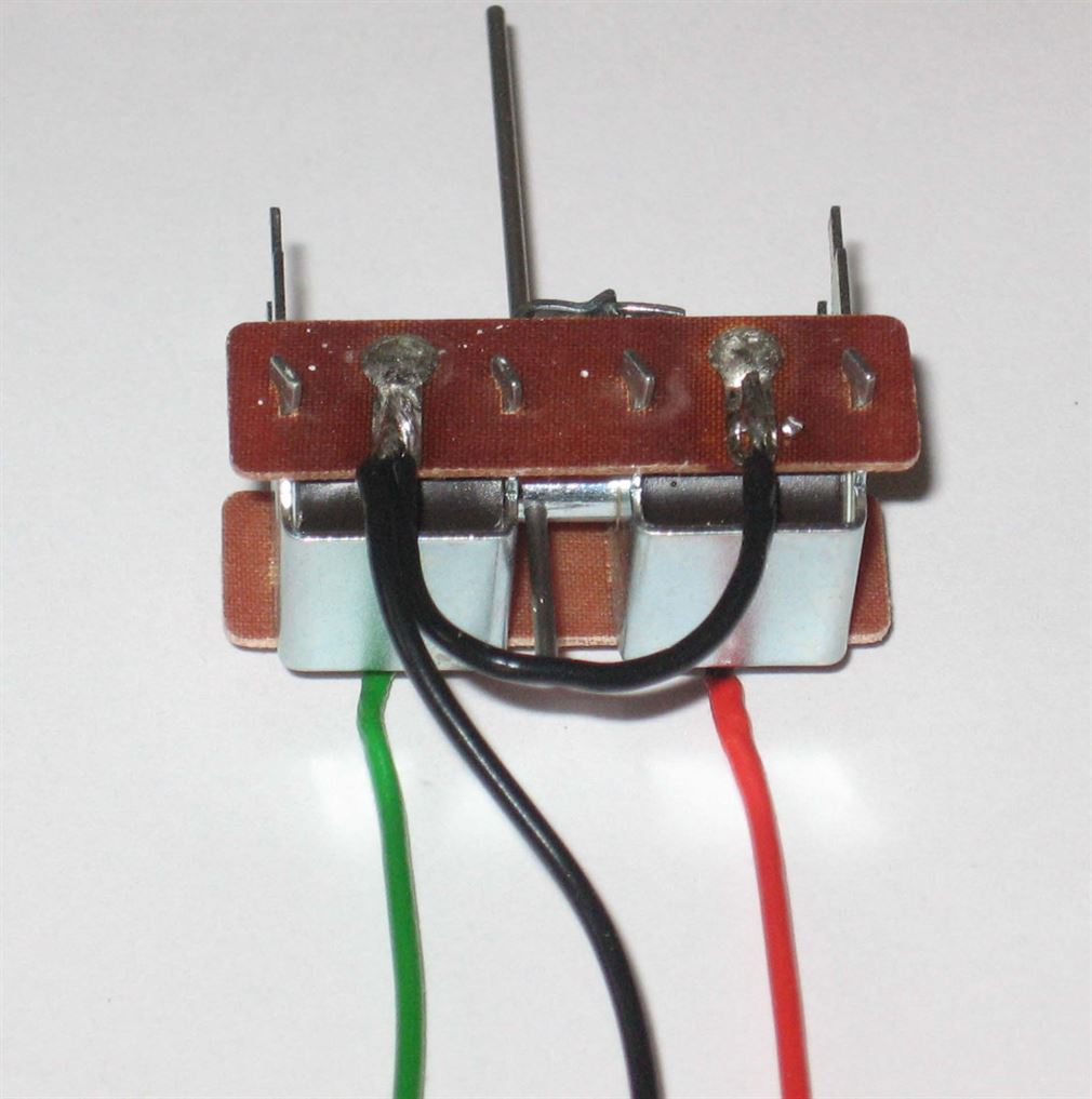
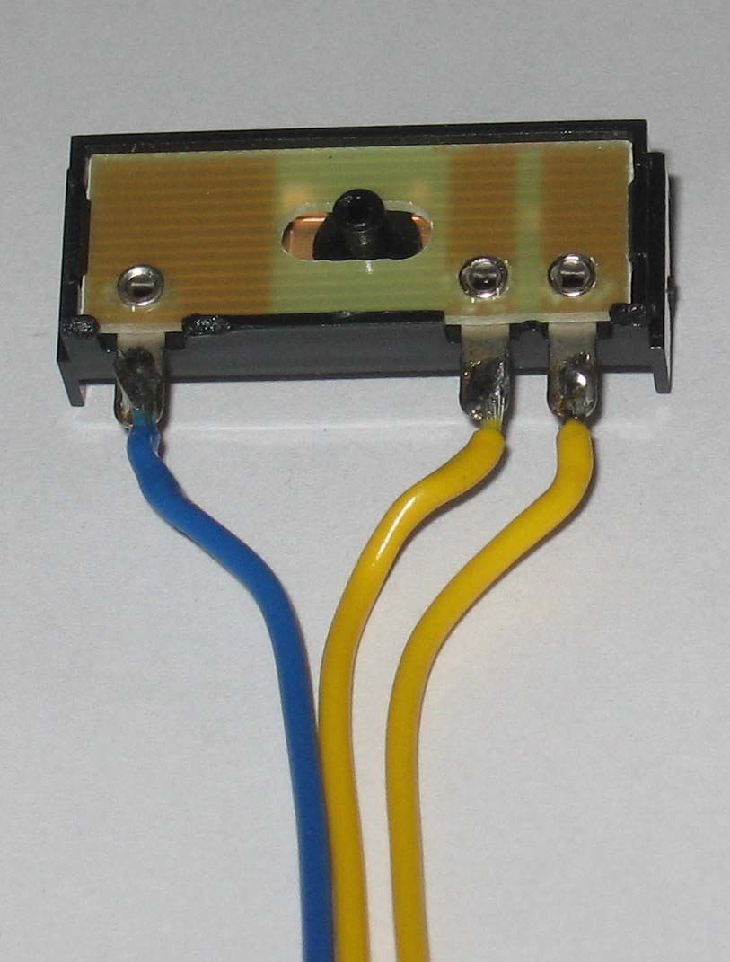
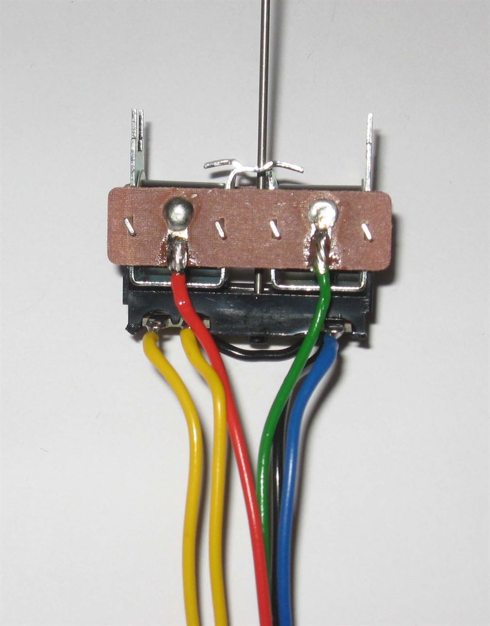
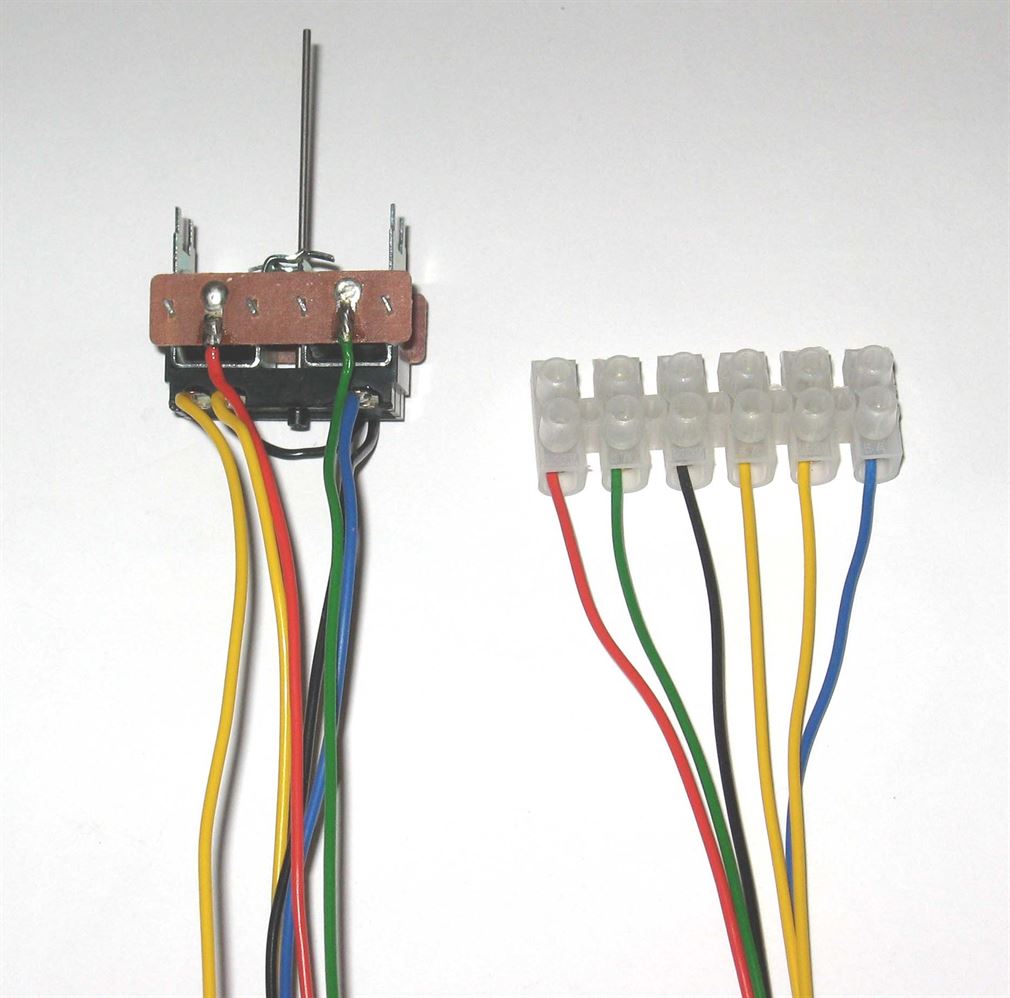
Above series of pictures shows… PL10E motor wires with its two operation wires (Red and Green) and the linked return connections wired in Black. Next is the PL13 switch then the pair ready to be joined together. Photo four shows the PL13 now fitted to the PL10E. Finally the motor wiring loom has been fitted with a six way terminal block to aid wiring and any later testing as needed. Note the 'E' of the PL10 this denotes its an Extended pin type.
With the motor and its contact block in place on the layout, the final wiring is connected to the opposite side of the 6 way terminal block. The three wires connecting to the first three terminals are all motor coil operation and the wires from T1 and T2 go back to the control panel or operation switch/lever, these form the operation wires, while a wire from T3 connects to the nearest Common Return location. Then wires on terminals T4, T5 and T6 are used for switching circuits as required. What these wires from the points switch block are used for is a matter of personal choice. I use them for frog polarity switching as I use live frog (Electrofrog) points, but they could be run back to the control panel and used to illuminate indication lamps/LEDs or possibly operate relays for signal and track feeds?
Live frog (Electrofrog) points, by installing frog polarity switching it ensures the ultimate electrical contact from the frog onwards and does away with the reliance put upon the switch blade to stock rail contact. If frog switching is used and the terminal block strip is also being used, then take one wire from the rail at the beginning of the point to the Normal terminal 4. Another wire from the opposite rail to the Reverse terminal 5 and finally a wire from terminal 6 to connect the two rails together just after the frog. Only one connection is in reality needed at the frog end, as the electrofrog links both rails together electrically. In the diagram both rails are shown wired (by the blue hashed line), but this is for diagram clarity only. If no terminal block is used, then connect the wires from the two rails before the point blades to the appropriate point operated switch connections and the wire from the frog rail connects directly to the common or moving contact of the change-over switch.
See the drawing….
For those who may choose to use Seep PM1 motors with built in polarity switching the drawing below is how they are wired into Live (Electro) Frog points.
By using either the factory fitted insulations or gaps or where no factory fitted insulations exist by cutting your own gaps into the two closure rails after the pivot point and before the frog, the live frog point becomes the best possible electrically.
The two gaps, if not factory fitted, are ideally cut by using a Jewellers Piercing saw for a finer gap or use an electrical mini drill fitted with a metal slitting disc. Note: This modification must only be carried out where Frog polarity switching is used.
The Peco 3 way point (Insulated and Electrofrog versions) ..
Below is show how the two motors of a three way point are connected via a simple diode matrix to three route selection switches and the CDU.
To note the reference to N= Normal or straight route and R= Reverse turnout direction.
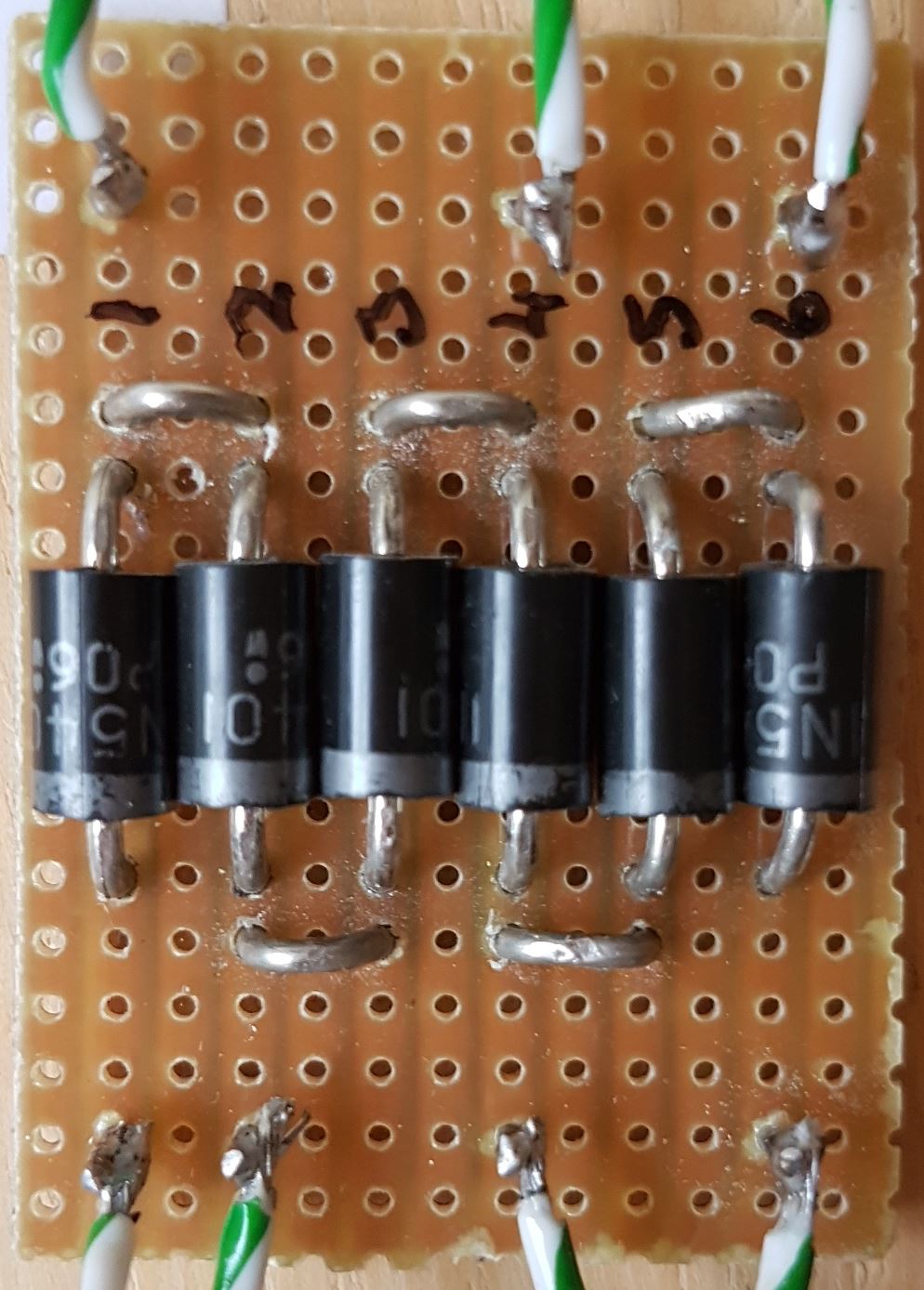
Wires shown marked with a red asterisk are not required for Stud and Probe selection. The Probe is connected directly to the CDUs positive output terminal and the "Sw" switches become the three Studs. Below is the physical layout of the matrix both on strip board and diagrammatically. Strip board copper track is cut through underneath each diode.
The Electrofrog (live frog) 3 way point often causes concern and confusion when layout builders try to wire one. I recommend that you use point motors fitted with at least a single pole change over switch (micro switch) or better still double pole switches or micro switches. Where the double switch is used one set of contacts undertakes the track feed switching of the frog(s) while the second set of contacts can be used for controlling signalling or indication of point position on a control panels mimic diagram etc.
The diagrams below show how the Electrofrog switching needs to be wired for live frog points. One type has three frog wires, one wire coming from each frog. While the other which is more commonly found has two frog wires.
The frog polarity switching and wiring is the same for dc as it is for DCC.
DOUBLE SLIP live frog (Electrofrog) wiring seems to cause problems. Below is the wiring diagram for these points. Note the motor switching to frog connection is at opposite ends of the slip.
Below is the same Electrofrog Double Slip but the tracks feeding into and out of the DS are from two separate DC controllers. A Double Pole Double Throw (DPDT) On-On switch is used to select which DC controller feeds the slip for a move through the slip and onward to the normally powered rails from that controller..
To wire the two motors that are needed to operate the double slip and assuming solenoid types are being used, then they can be wired as shown below.
DIAMOND CROSSING. The insulated frog diamond crossing does not require any special feeding arrangements as all track power freed is taken care of by the insulted frogs and the factory installed wires underneath the point. However the live frog or Electrofrog diamond crossing does require some special wiring and switching. Below is shown the wiring for a live frog (Electrofrog) diamond crossing. The drawing shows the crossing being wired for one track power supply feeding both directions or for manually switched DCC use a DPDT switch changes the two live frogs polarity. Note: for DCC use its really better to use an Auto Reverse Module - See the DCC pages.
Where two separate power supplies are involved, as in a dc twin controller, twin tracked layout, the use of a four pole double throw (4PDT) toggle switch is employed to switch the diamond crossings live frogs and provide track power to the Outer rails of the crossing. A 4 pole 3 way rotary switch could also be used with the central position being off. The toggle switch is set to the right to run from points 'A' to 'D' or the the left to run 'B' to 'C'. Normal frog polarity switching is carried out as per usual for live frog points (see above) via point operated switches. The 10 IRJs show are all required to provide isolation.
Unable to fit a Point operated change-over switch? Consider using a twin coil Latching Relay! A 12 or 24 volt twin coil latching relay used with a solenoid point motor that is fed from a CDU output or directly from a dc supply can have a latching relay wired across its operating wires. The latching relay can be positioned and connected into circuit anywhere from the operating switches output terminals, the wiring going off to the motor or at the motor itself. Its important to only use a twin coil Latching Relay. A conventional relay will not operate correctly.
The wiring diagram below is generic and shows the how the latching and un latching is fed from the point motor wiring. Diodes are fitted to ensure correct current flow and then works with DC or AC feed to the motor.
Relay and resistors I source from Bitsbox in the UK. Using their SW105 twin coil latching relay and QD036 diodes. Plus if wished to be used their MR11K 1watt 1K0 resistors. Link to Bitsbox https://www.bitsbox.co.uk/
In the above circuit when the red wire feed to the point motor is powered the latching relay energises and mechanically latches in the energised position and remains in that position even when the power is removed from the red feed wire. It will remain latched mechanically until a second pulse of power is fed to its unlatch coil via the green wire. This is when the point motor is moved over to the opposite direction. Note: The Peco PL11 and Gaugemaster PM20 motor wiring colours are different from those depicted above.
The same applied to the Peco PL10 motor fitted with a PL13 switch.
Similar wiring using a SEEP PM1 or PM4 motors with built in change-over contacts.
Below is shown a Live Frog (Electrofrog) point fitted with a SEEP PM1 motor. A relay is powered via the SEEPs contact. In this case the contact that makes connection when the point is reversed as this saves having the relay powered (energised) most of the time, as the point would sit in its normal position most of the time. The relay in turn providing both frog polarity switching and panel indications or signal aspect change-over etc.
For more complex indication arrangements then the circuit below uses a common 12volt positive dc feed run around the layout. Onto this wherever needed is a wire to feed off to the point activated switch's 'common' terminal. Two wires are then taken back to the indication panel and feed one or more LEDs as required per route. The points being Normal illuminates the straight route of LED/s and moving the points reverse then illuminates the opposite route or directions LED/s.
Basic one LED per route mimic panel wiring. Note as only one LED can be illuminated at any time then one series resistor is all that's needed per two LEDs...
Below is the same part of the mimic diagram, but here two LEDs are used per route direction. Note now that the two LEDs per route have a shared series resistors
To save on wiring, especially where a number of indications are being returned to the panel, a twin 12v dc bus pair of wires is fed around the layout carrying a 12volt positive and a 12v negative feeds from the uncontrolled output or perhaps from a separate power supply, as shown below. From each of the point operated motor switches two wires are run to and connected onto each of the 12v bus wires. From the point motor switch's 'common' change-over terminal there is then just one wire per point end going back to the panel (thereby saving one wire per point end over the previous wiring) and this illuminates the appropriate group of LEDs, which in my case 2 x 3mm yellow type. In addition, this twin 12 volt supply bus is used to power other accessories such as signal lamps etc.
Two LEDs are mounted into the mimic panels track diagram per route and both are feed via one resistor per LED pair.
It is important to note that in this circuit one route direction of LEDs are wired the opposite way from the other routes LEDs. Where a route is showing a cross over, from say up to down line, then four LEDs illuminate that route i.e. two per point end.
The three way point can be indicated on the mimic panel or other location if wired as shown below. If the 3 way point is of the Insulated frog type only one set of contacts per point motor is needed. If Live frog (Electrofrog) 3 way then a twin micro switch (PL15) is needed per motor, as one set of change-over contacts per motor will be used for frog switching while the other set is used for the indications..The alternative where the point switches are used for frog polarity is to use separate switches such as a pair of Latching Relays for solinoind motors. See design above. Linked here
Below is shown the mimic panel wiring for a Double Slip. Note that each point motor operated switch feeds an LED at the opposite end on the slips mimic diagram. Where an Insulated frog slip is used then a Single Pole Double Throw (SPDT) is all that needed at each end. This could be for example fed via a Peco PL13 or Seep PM1. Where an Electrofrog double slip is being used then a twin contact switch is needed - Double Pole Double Throw (DPDT). With one side of each switch feeding the indication LEDs and the other pair of contacts per motor feeding the points frog polarity. An example would be a Peco PL15 switch or a Stall point motor with two sets of change-over contacts fitted is required.
Finally for those who like to see a Red LED lit for the unset route and a Green for the set route that swaps around as the route alters then below is a drawing showing the LEDs and their wiring. It should be noted that the two drawings show on the left LEDs operated by a Positive feed and on the right LEDs operated by a switched negative which is frequently used on many electronic devices. But do double check on how any pre made device outputs the feeds or returns before connecting the LEDs.
If the modeller wishes to have two LED indication states from a single LED, then consider using a three wire Bi-coloured LEDs.
There are several LEDs that a can be used for this. The main two are common Anode or common Cathode three lead LEDs. The common being the middle lead of the three. Below is show the basic wiring for both types, note a Seep PM1 is used in the examples but the Seeps contact can be replaced by any change-over type of double pole switch. Note: The two wire Bi-colour LED requires a more complex circuit that involves reversing the polarity to the LED. The three lead type of LED are simpler to wire.
Diode Matrix is the means by which multiple solenoid point motors can be route selected from one non locking push button, momentary switch or if used, the stud and probe method of selection, on a mimic panel.
Once your track plan has been finalised and the routes needed are visible, from the plan, you can work out which points need to throw over for a train to travel from place A to B or A to C etc. Before you commence drawing the matrix you will need to understand the terminology used to show which way a point is to be set. Use ‘Normal’ or ‘Reverse’, the Normal position is often the straight direction through the point while Reverse is the direction via the curved part of the point. Then decide on how many push buttons are required, then number them logically. Number or alphabetically identify the point ends too.
Now create a “Truth Table” of point operations. This is just a simple written reference e.g. Pressing button 1 will cause point motors 1, 2, 3 & 4 to operate to Normal (N) or their Reverse (R) positions as needed.
Next and with the aid of the basic matrix grid (See drawing 1 below) draw a series of horizontal and vertical crossing lines in a grid formation. The number of horizontal lines (Rows) are equal to the number of push buttons and the number of vertical lines (Columns) are equal to the number of point motor coils (there are two coils per solenoid motor), wherever a point is required to move direction draw a connecting line (the point motor feed) from that buttons feed line (The horizontal line) to the motors coil (The vertical line). Then check the number of lines drawn in each of the vertical rows (columns). Wherever there is more than one line drawn in a column row, all the drawn lines in that row must become diodes. Where only one line is drawn in a column row then that is a wire link.
Redraw the matrix, now showing the diodes and recheck your matrix to the truth table created earlier for all the required moves. This is shown in the second drawing below.
Finally, convert the matrix drawing onto a ‘Strip board’ (Copper strips on the reverse of a pre drilled Paxolin board, sometimes called an SRBP Matrix Board) this is where the diodes and wire links can be soldered and the wires from the push buttons and output wires to the motor coils are all connected. It is wise to add adjacent rows of copper track strips to the main track where two or more motors are to be operated together these added strips allow for the increased current flow occurring. These extra tracks are simply wire linked top and bottom to technically make all the strips linked become as one.
The final and third drawing shows the matrix strip board with the diodes and wire links etc fitted.
Note: Diode Matrix point operation must be fed from a Heavy Duty Capacitor Discharge Unit (CDU) as there is the requirement to throw several motors over all at once. Ideally the input voltage to the CDU should be a minimum of 16 volts AC or 19 to 24 volts DC. All diodes are 1N5400 or 1N5401 3amp rectifier diodes.
CDUs (Capacitor Discharge Unit) These often are purchased as either Standard or Heavy Duty types. The 'Standard' version will throw up to 2 or 3 point motors simultaneously while the Heavy Duty variant will normally throw 6 plus motors all at once. Normally only one CDU is needed for the whole layout. Equally a CDU can operate just one solenoid motor at a time.
The CDU delivers a heavy pulse of electrical power to the point motor's coil. This pulse is much larger than can be obtained by the nominal 16 volt AC power supply. A CDU will help the solenoid motor move over better and also overcome any stiffness in the motor, its operating mechanism or in the actual point itself.
Under non CDU operation, a point motors coil would normally burn out if left powered continuously for a short length of time! Once a CDU is placed in circuit and it is discharged it then helps prevent motor coil burn out, as only a small limited current is able to flow into the coil.
The CDU recharges once the operating switch has been restored to the Off position, where upon the CDU is then ready for the next point switches operation. Ready made CDUs are sold by all good model shops or via model railway internet shops.
Note; CDUs are not normally used with DCC accessory decoders, as in most cases these can have a CDU built into them. But always check with the accessory decoders manufactures specification sheet to see if one is factory built in or not.
A CDU can be constructed from some basic electronic items and even a version that will throw several motors can be made for a couple of pounds. Shown below are the basic and advanced CDU designs. Where a heavy duty version is required increase the capacitor to 4700uf or use two 2200uF capacitors in parallel. Note the capacitors should be rated at at least 35v or higher volts.
In the above two circuits the top version is the very basic CDU and takes a short while for the capacitors to reach their fully recharged state, while the lower is a more advanced design using a transistor to switch the power. Two type of suitable transistor are shown. TIP3055 or 2N3055. In both, resistor R1 restricts the current flow to the motors coil once the CDU has discharged.
Below is shown the stripboard layout for the advanced CDU. Note the 2N3055 transistor if used, needs mounting off board and ideally on a suitable heatsink. However, I would recommend the use of the TIP3055 transistor for its ease of mounting directly onto the stripboard.
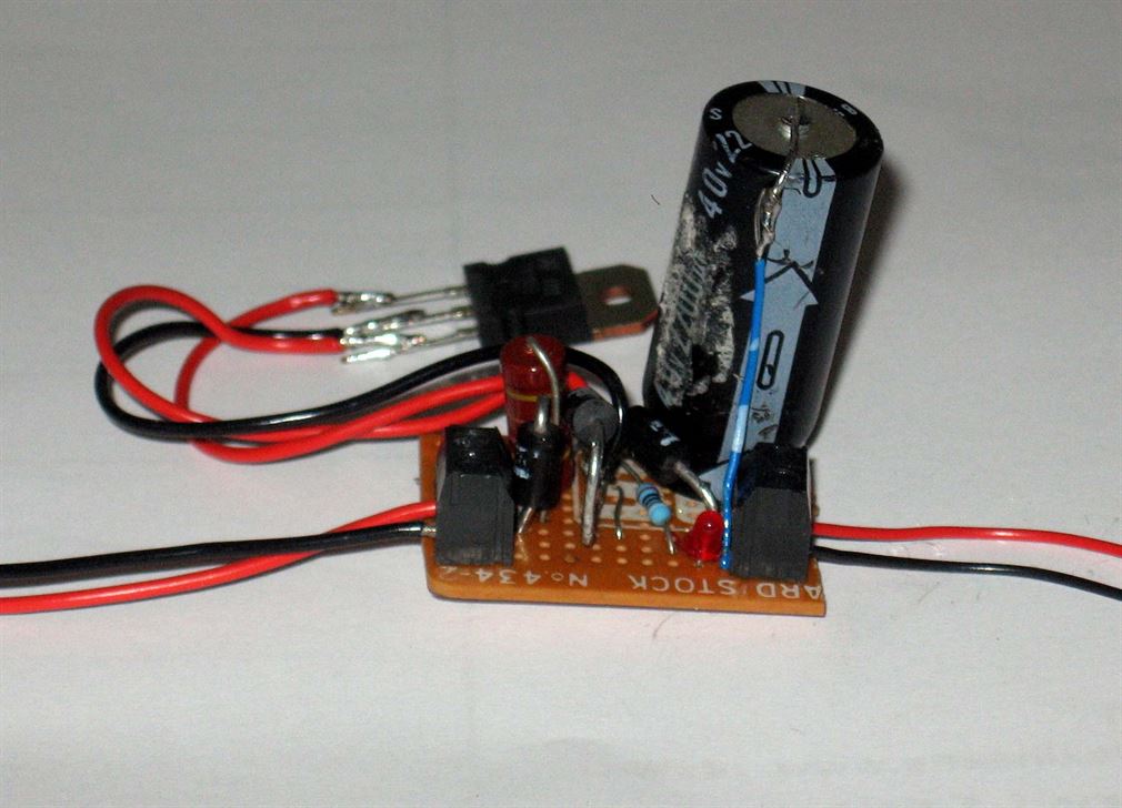
The picture below is the original prototype CDU. The TIP3055 transistor is connected by temporary wires to the circuit board and one 2200µf capacitor is used. When the CDU has been discharged into the point motors coil, a small 0.015millamp current flow remains flowing through the motors coil, this is not enough current to cause coil burn out and would normally only occur should the switch remain in the On position.
Now for all the rest of the wiring….
Signals & Lighting....
Series and Parallel.
What is meant by the terms "Series" or "Parallel" connected?
Series connections can simply be likened to that of 'daisy chaining' the items together, this can be any number if items from two up. Series connecting filament lamps together will allow several lamps to be fed from one supply volts where the individual lamps voltage is below that of the supply. Series connecting resistors together will increase there total resistance, while capacitors connected in series will reduce their overall capacitance value.
Parallel connection can be likened to having two supply rails or bus and each item is connected across the pair of buses or rails. The items being connected on a dc circuit are connected between positive and negative supply paths. Lamps connected in parallel must be rated at the same voltage as the supply is at. Resistors connected to a circuit in parallel have there total value reduced while capacitors connected in parallel have there total value increased. A single item can only ever be connected in parallel, as for it to work it must have a feed and return. Confused?
The drawings below show examples of connection styles and perhaps make it a little easier to understand?
The drawing below is showing a simple example of how filament lamps of different voltages can be connected to a feed pair of wires. Note where two or more lamps are series connected across the supply, should one lamp fail then all in the group will go out until the failed lamp is replaced.
By adding together the lamps rated voltage in a group, and so long as their combined totalled voltage is exactly the same as or a little higher than the supply volts, the lamps will illuminate at their rated voltage correctly.
The order in which the groups are connected along the supply wires doesn't matter. All that matters is each lamp or group of series lamps total voltage equals or is a little higher than the supply volts.
Example:If the supply volts was 12 volts then normally you would wire in series 3 x 4volt filament lamps (3 x 4 = 12) across the supply, but you could series wire four 4 volt lamps across the supply as 4 x 4 = 16 which is a little higher than the supply of 12v. Each lamp then will not illuminate to its full brightness but will still provide a good level of illumination and each lamps longevity in that group will be much greater than if only three 4 volt lamps were in series.
What power supply do I need to run my lamps?
To obtain a correctly sized power supply unit or PSU we need to know the current or wattage of each lamp to be lit then times that by the total lamps illuminated. Many Grain of Wheat or Grain of Rice lamps are in the 50ma (0.05A) to 70ma (0.07A) range. Each lamp can easily consuming up to 0.07Amp from the supply. So the total number of lit lamps is added together to obtain the total current load being placed on a power supply.
Example: Ten x 70 milliamp lamps all lit will draw 700millamp or just a little under 3/4 Amp. (10 x 0.07 = 0.7 or 700ma).
Ideally use a power supply that provides dc (direct current) output, this will allow both filament lamps and LEDs to last longer. ac (Alternating Current) PSUs can be used but often their output volts are in model railways found to be higher - typically 16 volts ac.
But the very first thing is to determining what is the exact voltage of the supply? The specification label isn't always correct or accurate!
If the supply is being fed from a ‘Regulated’ dc power supply the voltage available will be within a few millivolts of that specified, regardless of the loading and can be taken as read on the spec. label.
But if its supplied from say a model railway controllers 12 volt auxiliary output or even from the actual 12v controlled output of a controller or any other plug-in style of power supply, the actual voltage is very likely to be above the stated voltage. So typically a non regulated nominal 12 volt supply may be found to have 15 or 16 volts on its terminals off load or with little load applied and only falls to the 12 volts when its nearing its maximum rated loading.
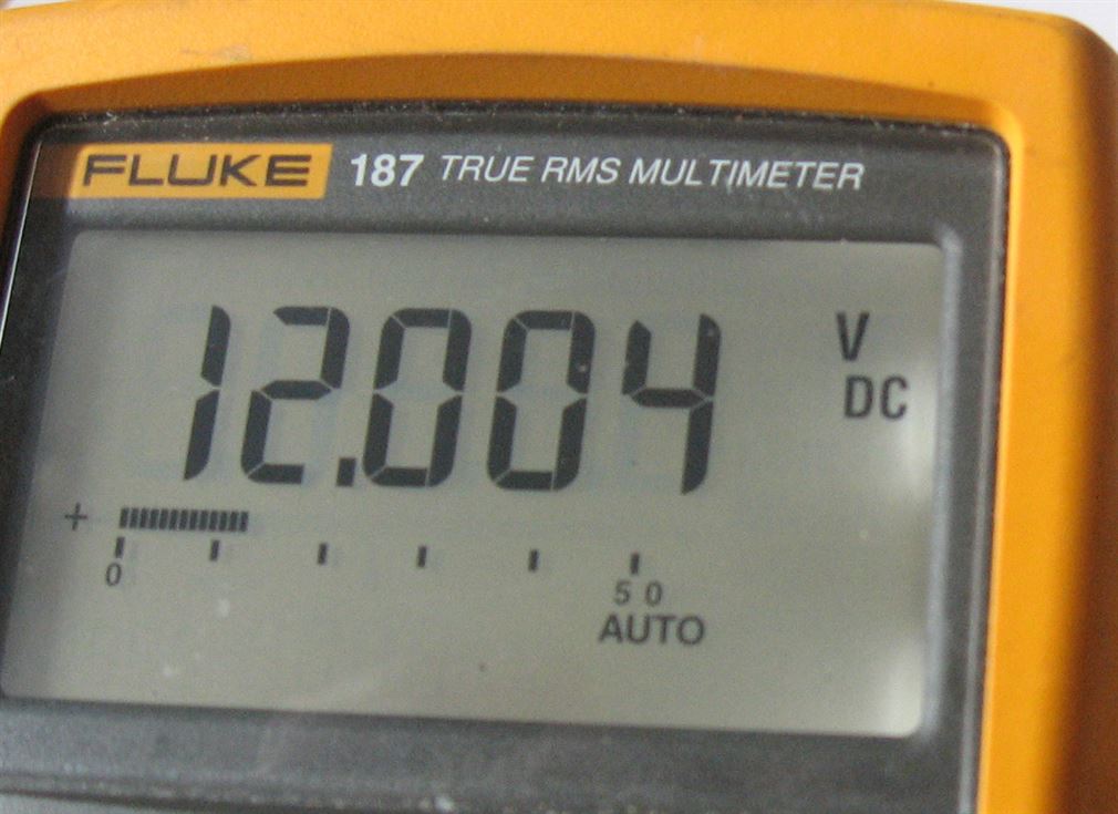
So where a non regulated power source is to be used its good practice to actually measure the DC voltage being supplied.
Use a multimeter to measure this. These do not have to be expensive meters and often a 'home user' style of digital meter can be obtained for a few pounds and often less than £15 GBP. These will be able to measure dc and ac voltages, read dc current and take resistance readings as a minimum. But often a cheaper multimeter will not be able to measure ac current flow.
So knowing our true supply voltage is quite important if we want the lamps to last any length of time.
What is the wattage of my lamps? This is a simple sum... Multiply the lamps rated voltage by its milliamp rating e.g. A 12v lamp x 0.07ma = 0.84watt. Or if a 6volt lamp then 6v x 0.07ma = 0.42watt.
What is the current if I only know the lamps wattage and voltage?.... Divide the specified wattage by the rated voltage e.g. 0.84w / 12v = 0.07A or 70 milliamp. Or if 6volt then 0.42 / 6 = 0.07A (70milliamp).
Once we know the voltage and the wattage or current of the filament lamp were able to determine the power supply needed. Simply times the Amperage (Current) of each lamp by the number of lit lamps. e.g. 20 lamps to be lit times 0.07 equals 1.4 Amp. Use a PSU that can provide above this current, so opt for at least a 1.5Amp or better still a 2.0Amp PSU.
Note: Most train set controllers can not provide this current and will normally cut off the feed immediately or within a few seconds due to the overload device operating inside the controller protecting its transformer etc.
But what if the filament lamps are rated less than the supply voltage? Example 6 volt lamps each rated at 0.07 (70 milliamp) are purchased but the power supply is 12 volts.
We can overcome this in one of two ways.
Connect two 6volt lamps together in series (daisy chain them) by connecting one lead from each together and then connect the remaining two leads across the 12 volt supply. Each lamp receiving 50% of the available 12 volts or 6 volts each. Problem here is if one lamp fails both will go out.
Or use one series resistor per lamp.
The 12 volt supply is then reduced by the resistor to a voltage level acceptable for the lamp to work correctly. But the correct value and wattage of resistor is needed or the lamp will be over fed with volts or the resistor will get hot - very hot if its below the correct wattage value required. It may even burn out if not correct!
In this example a single 6 volt 70ma lamp is to be fed from 12 volts DC A series resistor value is calculated by... Supply 12 volts minus the 6 volts of the lamp divided by the current of the lamp or 12-6 = 6. So 6 / 0.07 = 85.7 OHMS. Here we should use the nearest available larger OHM value (Preferred value) of resistor to the answer. In this case a 100 OHM (100R) resistor will be fine.
Now the resistor wattage rating must be taken into account. As we saw earlier from the calculation the 6volt 70milliamp lamp is consuming 0.42watt. Almost 1/2 watt. So our 100R resistor MUST be rated higher than the lamps wattage. Here a 1/2 watt or 0.6watt resistor will be fine or a resistor with a higher wattage would be even better to use and wont get as warm as a 1/2 watt would.
To note; increasing the OHM value of the resistor will reduce the lamps brightness and lowering its value will increase the brightness, but do not allow the lamp to be fed with more voltage than its rated at. Ideally always feed a filament lamp with a lower voltage than its rated at. It will last much, much longer if its volts are reduced!
LEDs
LEDs (Light Emitting Diode) come in all sorts of sizes and brightness. from tiny 0.5mm wide surface mount devices (SMDs) to the huge 10mm or bigger versions, they run virtually cold and last for many years and they all work on the same principle. Apply the correct dc voltage the right way around and the LED will light! It is applying the correct voltage and limiting the current available that often causes so much problem! In the main, most basic 3mm or 5mm dia. LEDs require around 2.2 volts (Red, Green, Yellow and Orange are typical) White LEDs need a higher voltage often around 3.5 to 4.0 volts. Most LEDs will illuminate at around 5 to 20 milliamps of current flowing.. There are exceptions, but these figures apply to most normal LEDs. So, how do we run an LED safely from our power supply? Simply we fit a suitable series resistor in circuit! It is always best to fit one resistor for each lit LED. To calculate the value of resistor needed there is a quite a simple formula to work this out... Lets take the power supply as being 12 volts d.c. The forward voltage of a standard LED is around 2.2 volts and its ideal forward current is around 20 milliamps. Note: these values can vary and the manufactures data sheet will give the exact values. So, the formula is :- 12v (the supply voltage) minus 2.2 (the forward LED volts) divided by 20ma (the forward LED current) hence the sum is 12-2.2/0.020 This equals 12-2.2 = 9.8 divided by 0.020 Which gives an answer of 490. This answer is the minimum value of the resistance needed. Unfortunately resistors aren't available in this value! The nearest above is 510R or 560R (ohms). So you chose either one of these to run the LED at its safe maximum brightness. Higher value resistance can be used and these will, as the resistance value increases, cause the LED to run less brightly. Remember that LEDs are polarity conscious devices, therefore when connected to a dc supply (with suitable resistance) they will only illuminate when the positive supply is connected to the correct LED wire or Anode (normally the longer lead of the two).
If you want to run an LED on a.c. then either fit an inverse diode wired across the LED and the resistance value calculated by the above formula is then halved. Or use a series diode in the positive feed wire to the LED. Note, LEDs will illuminate on an ac supply (not really recommended) and there brightness may will be reduced, as too will their longevity. A series resistor should always be fitted too. AC LEDs are also available but are not that common.
A handy LED resistor value calculator is located here LED wizard But you will need to know the supply volts (Vs), the LEDs forward rated volts (VF) and its maximum rated current (IF).
Typical multiple LED Wiring.....
In the above series connected configuration add together the LEDs rated forward voltage so as the chains total does not exceed the supply volts rating.
At times on lighting circuits etc there is a need to reduce the supply volts to enable a bank of lighting to operate safely without having to wire lamps in series. On dc supplies this can be easily obtained by using diodes. By connecting several diodes in series to themselves the supply volts is reduced by each diode in turn. Normal Rectifier diodes -1N400x 1Amp or 1N504x 3 Amp range, where x = a number 1 to 7 or higher which is the diodes maximum reverse blocking voltage (See data sheet) are frequently used. Each diode will reduce the voltage by 0.7volts, so by connecting them in series the dc supply volts can be reduced to that required. In the example below four diodes are series connected giving a total drop of 2.8 volts. But of course the supply volts can be tapped off at any point after one or more diodes to give a 0.7 volt reduction from the previous. The only thing to ensure is that the diodes used can pass the maximum current needed. Reference to the suppliers data tables for a particular diode will show exactly the maximum current that type of diode can pass safely.
I run a 12 v d.c. supply around the boards, as I use this for colour light signal aspect illumination – the relays do the switching of aspects. At each place where a connection is required I break into the circuit and feed the appropriate signal relay etc.
Additionally a 16volt AC supply is fed around the layout too.
Signalling.
2 Aspect. Below is the very basic two aspect signal, lit by LEDs and fed from a 12 volt dc power supply. The change-over switch can be a Hornby R046 yellow On/On type. Or a Peco PL-23 even a Single Pole Double Throw (SPDT) toggle switch. Note the voltage and current limiting resistor fitted in the return lead, as the LEDs used here are rated at 2.2volts. The signal shown is a typical Eckon/Berko two aspect.
Hornby R406 CL signal notes: The wiring supplied by Hornby in my opinion defies logic! They use Red wire for the red aspect feed, Black wire for the Green aspect feed and Green wire for the return!! The series resistor shown is not needed with the R406 as it is built in. The R406 now uses LEDs in place of filament lamps too. The R406 is vastly overscale compared to more true OO scale signals from Eckon/Berko or other UK manufacturers!
In the drawings below, I have shown again a simple two aspect colour light signal, but one is directly controlled via a Double Pole Double Throw (DPDT) toggle switch, while the lower one is similar but controlled by a 12v (coil volts) relay with two sets of change over contacts – Double Pole Double Throw (DPDT) contacts. Here the relay both operates the signal aspects and turns on/off the track power to the signal approach isolating section i.e. Signal at red - track section off, signal at proceed - track section on (fed normally). The use of the relay means only one wire is needed to run from the switch to the relay which is located as close to the actual signal and isolating track section as practicable.
The relays use is two fold. Firstly, it saves on wiring between the control panel switch and the signal – Only one wire is used where two would be needed if direct control were employed. Secondly, it provides multiple switching facilities. So it can both change aspects and operate the track isolating section at that signal. Where relays really win is when a four pole relay is used - 4PDT type. This is where the extra contacts can be used for switching other functions, controlling three or four aspect colour light signals and ensuring aspect sequencing is correct.
Aspect sequencing -
Two Aspect signalling... The Home signal is capable of displaying a Red or Green aspect (some can display a red and a yellow in place of the green aspect). On the approach to the Home signal is placed a Distant signal which can show Yellow or Green aspects. So with the Home signal at Red the distant displays a Yellow aspect. With the Home signal at a proceed aspect - Green (or Yellow), the distant displays a Green aspect.
Three aspect signalling... Each signal is capable of displaying a Red or a Yellow or a Green aspect - only one of the three can be lit. So our first signal is at a Red (1), next signal back is at Yellow (2) and the one behind that (3) at Green. When signal (1) steps up from Red to a Yellow aspect, signal (2) follows by stepping up to a Green and signal (3) remains at Green.
Four aspect signalling... Each signal is capable of displaying a Red, or a Yellow, or a double Yellow, or a Green aspect . The sequence is - First signal at red (1), next (2) at one yellow (lower yellow aspect lit) next signal (3) at two yellows, fourth signal (4) at green. When signal (1) steps up to a single Yellow, signal (2) steps up to double Yellow, signal (3) goes to Green and signal (4) remains at Green. When signal (1) steps up to a double Yellow, all signals on its approach (2), (3) & (4) are at Green.
Blow a diagram of basic colour light aspect sequencing, the use of two, three and four aspect signalling is shown. These operate in a specific sequence as described above and this portrayed in this diagram......
3 Aspect The simplest form of controlling a colour light three aspect signal is via a rotary switch. A four pole three way (4P3W) rotary switch is used fitted with a suitable knob. The switch is wired as below and when turned to one of its three positions it controls the appropriate aspect of the signal. The rotary switch is shown in its middle switching position - illuminating the yellow aspect.
Below is shown a Live Frog (Electrofrog) point fitted with a SEEP PM1 motor. A relay is powered via the SEEPs contact. In this case the contact that makes connection when the point is reversed as this saves having the relay powered (energised) most of the time, as the point would sit in its normal position most of the time. The relay in turn providing both frog polarity switching and panel indications or signal aspect change-over etc.
Four aspect colour light signals can be operated through the use three pole four way (3P4W) rotary switch. The second or top yellow aspect must only illuminate when the lower yellow aspect lit, never on its own. To allow this a diode (D1) is used which provides a feed path from the 2nd yellows switch position to the lower 1st yellow feed, so allowing both aspects to remain lit when the switch is in the 2nd yellow position. Note there is also need for a second resistor wired into the return path of the top yellows LED. The other resistor serving the three other aspects. The value of the two resistor should the the same - typically 1K0 1/4watt.
This is shown in the wiring diagram below which is for an Eckon/Berko or other Common Cathode signal..

For a more semi automated system of aspect control where several signals are used, the wiring for a series of sequential three aspect signals is shown below in two variations.
Note that when the panel switch for that signal is turned off no relays are operated (energised) and the signals red LED illuminates via the green and red relay contacts not operated. Also the signals Isolating section of track is disconnected (Isolated) by a separate contact in the red/yellow relay. Operating the panel switch to the 'on' position causes the red relay to operate (energise). This provides an electrical path to the green relays coil and also changes the signals aspect to yellow via the red relay operated (energised) and the green relay not operated (de-energised) contacts, This assumes there is no feed coming from the next signal ahead - i.e. its at red. Power to the signals track isolating section is also restored. When the signal ahead steps up to either a yellow or green it provides a 12 volt supply to this signals green relay and assuming the red relay is still energised, the green relay can then also energise. This now changes the aspect and lights the green LED via its own relays contact closing. So, we have a three aspect signal checking the signal ahead for its aspect and also sending a supply to the signal behind when our signal is at either yellow or green. This is automatic sequencing of aspects with control of the red. Only one wire is used from the control panel per signal, the 12v dc common feed supplies everything else and of course everything returns via the common return circuit wiring. Two relays are used, one with four sets of change over contacts (R/Y Rly) and the other (Green Rly) can have either two or four sets of change-over contacts. Both relays ideally should be located directly under where the signal is placed on the baseboard to make local wiring easier. Simple eh? If you’re not electrically minded don’t even think about four aspect signalling, as a third relay is needed at each signal! Alternatively, consider the use of the Heathcoat Electronics MAS-Sequencer-4 and / or their IRDASC-4’s details can be found via the Heathcoat link on my ‘Links’ page.
For those who prefer, the above wiring can be altered to make just a series of Double Pole Double Pole (DPDT) toggle panel switches operate in correct aspect sequence order any number of three aspect signals. The wiring is as shown below...
Where LEDs are used, they must be wired the correct way around. That is with their Anode leads to the inputs from the switches and their Cathodes all connected together then onto a series resistor before connecting to the 12 volt negative supply.
Electronics.
Other scenic effects include welders, flashing beacons, lighthouse illumination and sequentially (running) lights used on a recently made fair ground display on another of my ex club layouts, all add to the layouts realistic atmosphere. All of these I make myself using mainly the faithful NE555 or its bigger brother the dual NE556 timer microchip.
To ensure these electronic modules operate correctly a regulated and smoothed dc power supply is needed. I use the readily available LM7812 positive voltage regulator or the LM317T variable regulator to do this work. They only need only a few external components and offer a cheap and reliable regulated supply.
One thing to remember with all voltage regulators is they must have at least 2.0 volts or more at there input than the output required e.g. A 12v dc output will need at least 14v dc or higher input. Always fit a cooling heat sink to the regulator unless only very low current is to pass through it.
Below is shown a simple voltage regulator using the LM7812 device, this can be built either as a free standing unit or incorporated into a project such as the Welder as further down this page.
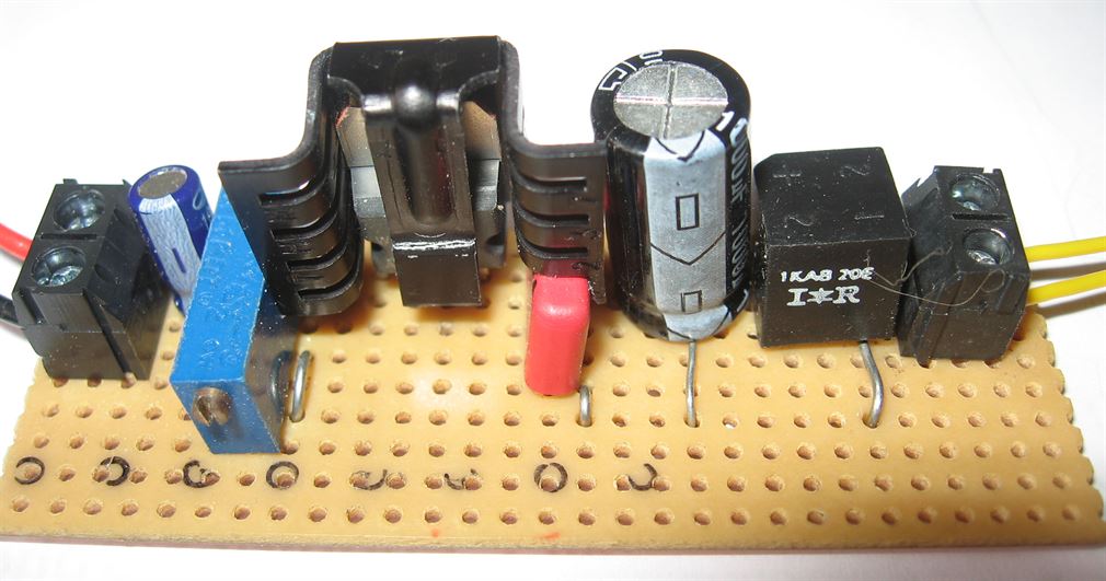
Shown below is the circuit and pictures of the variable voltage regulator, based on the LM317T device. This circuit can operate from a dc or ac input as a full wave bridge rectifier has been included in the build. It offers a manually adjustable, but then constant output voltage, from around 1.3 volts up to just below the input voltage, which in most model railway cases is normally 16 volts ac or 12volts. The output voltage, once set by VR, will remain constant regardless of the current loading (up to its rated maximum). The unit offers a maximum output current of 1.5Amps depending on the power supplies current rating. This regulator is ideal for controlling the voltage fed to illuminated accessories, such as station, street or yard lamps etc as it allows the output voltage to be reduced to allow longer filament lamp life. e.g. a 12 volt rated filament lamp will be virtually as bright if run at 10 volts, but will last much longer!
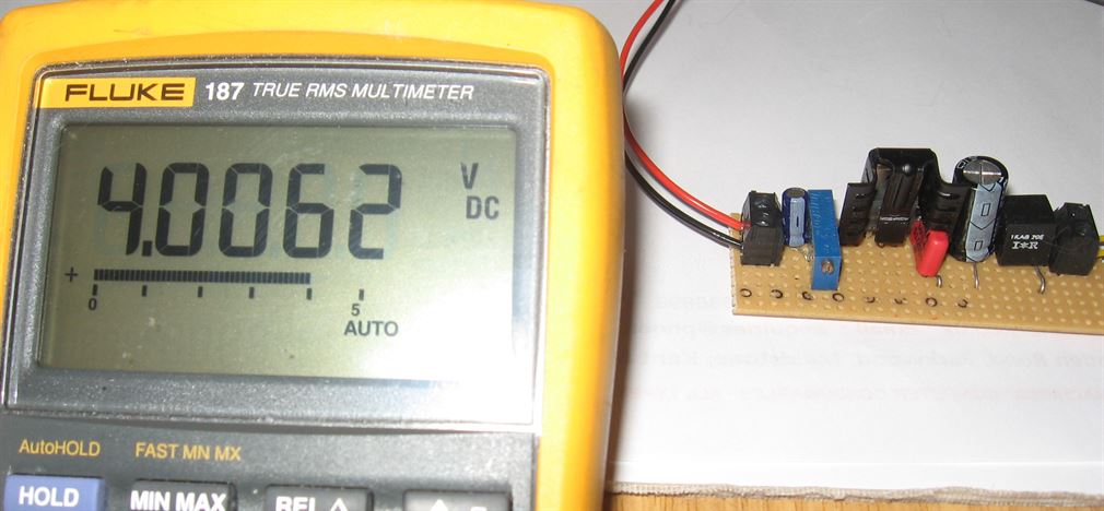
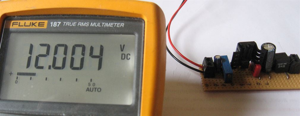
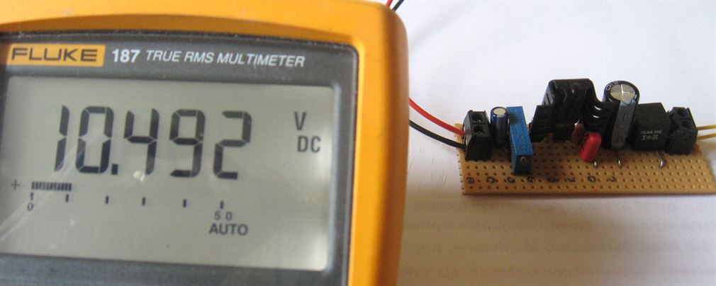
The pictures below show the completed variable regulator. In the first picture the assembly has been made up on a 29 x 10 hole strip board (though a minimum of 28 x 7 will do). In the second, third and last pictures some sample output voltage adjustments have been set via the Cermet pot, in these cases to give 4.0 volts, 12 volts and 10.49 volts respectively. The input used throughout was 16 volts ac.
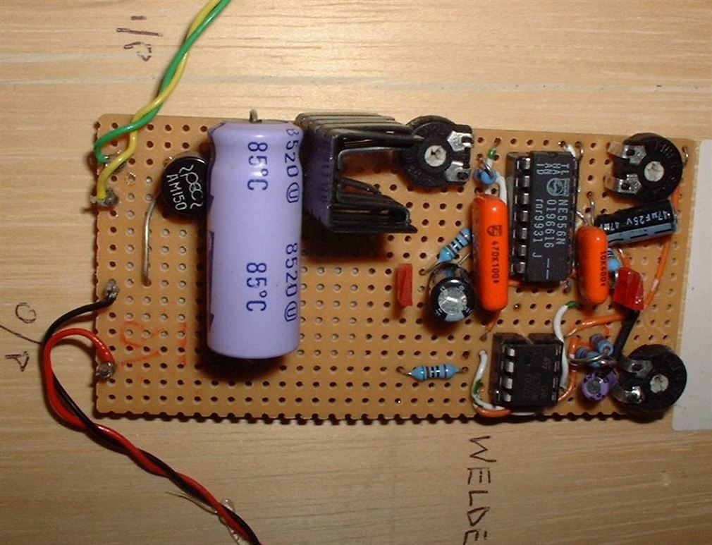
I enjoy making animated electronic effects and the arc welder is probably the most effective. A super white; ultra bright 3mm LED is the light source and gives a really excellent flash to represent an electric welder being used. When the LED is suitably hidden from view and then powered for a few seconds, the rapidly flashing light catches the viewing public’s eye (Not directly shining into their eye though!) and people cannot it seems wait for the next bout of welding to start again!
The wiring diagram above shows a complete electronic welder. In practice 16v ac is feed into the two input terminals and this is rectified and passed onto a 12v voltage regulator. This gives the circuit a constant 12v d.c regardless of any variations in the 16v a.c supply (which is often floating around 18v to 20v a.c.) IC-1 is a NE556 dual IC. One half of the chip acts as Astable Oscillator and controls the duration of the time cycle between welding flashes. The other half of the 556 works as a Mono Stable one shot timer and controls the length of the welding flash. The output from the second half of the 556 (Pin 9) supplies a pulse to the NE555 single chip timer which I configure as a Astable Oscillator, this controls the rate of the welding flash. This is variable via VR3 and is nominally set to a flash rate of around 10 to 20Hz. The welding flash duration is approx. 3 seconds, this restarts after a variable delay of around 7 to 20 seconds – determined by VR-1. The light source is an inexpensive high brightness white LED. These have an illumination intensity of around 3.2cd. I have produced numerous ‘Welding Kits’ for myself and friends.
Note: The components used in the photographed circuit board may not be exactly the same values as detailed in the circuit diagram above. This is because when I build a flasher circuit I use whatever components I have to hand in my 'bits box'. Example: Using slightly higher rated uF values of capacitors shouldn't harm the circuit, but may involve more 'fine tuning' via the variable resistors due to possible timing changes.
Train Control.
Several methods of controlling the speed and direction of a train are available.
These range from a simple battery operated switched controller, resistance controllers, transistorised and feedback controllers to the latest DCC systems. I’ll try and cover all but not in any specific detail or preference.
Battery controller: Probably the simplest of all. Connect the batteries (normally two of more) giving a total of around 12 volts dc and turn the knob. The knob connects to a simple switch and resistance network which together offers two or more steps (notches) of controlling power e.g. Off –low –medium-fully on. These may incorporate a reversing switch too.
Resistance Controller: Power is fed into a variable resistance mat onto which a wiper arm turns and picks up power continuously as it sweeps over the windings on the mat. Turning the knob up decreases circuit resistance and smoothly gives control over speed. H&M, early Hornby, and Tri-ang controllers all employed this very reliable method.
Transistorised: Works exactly the same as the resistance controllers but dispenses with the resistance mat and uses a transistor/s to slowly increase voltage to the rails as the knob or slider is moved which is altering the resistance value of a variable potentiometer.
Feedback: Works the same as the transistorised controller but uses transistors or Integrated Circuits (ICs or so called microchips) to monitor the back emf currents being generated from the electric motor of the train. This type of controller offers virtually constant speed up or down gradients by continually increasing or decreasing the supply output. Early ‘can’ style motors didn’t like these controllers as it caused them to overheat. But now the vast majority are ok to use with feedback controllers. Operates much like the Cruise Control on a car trying to keep the looc at aconstant speed regardless of whether on the level, up hill or down hill situation.
DCC (Digital Command Control): The latest technical innovation to hit the model railway layout. Early versions included the Hornby Zero One and the Airfix MTC both of these systems have been out of production for many years now. DCC of today not only offers the operator the smooth control of one train but you can control many other trains too, all on the same track/s plus control accessories such as lighting and point motors as well. What all this basically means is that digital signals are continually sent down the two rails, picked up by every loco on those rails and then passed via the wheels to an onboard decoder. Each decoder has a unique address which is set by the owner and when the appropriate digital frequency for that programmed decoder is received, that and only that, loco responds to the controllers setting. Once set going the DCC controller has the ability to be reprogrammed to another digital frequency and set a completely different loco moving, leaving the first travelling at the speed last set. NOTE: I have used the term “Frequency” but technically this isn’t true, it’s a stream of series data (data addresses) that’s doing the control. But that’s getting into the technical side! This link takes you to my DCC Page
I have built my own simple transistor controllers and used them very successfully on my former exhibition layout – Ridgley Vale and they were used in the fiddle yard. Two were used (one for each direction) continually during exhibitions for an average 6 hour day without ever failing! Below is the circuit diagram for one controller. I built mine on ‘Strip board’ and mounted the variable pot (controller knob), and two LEDs remotely connected to the circuit board via short length of screened cable. The distance must be kept short – not more than 6 inches ideally! The main transistor, a MJ2501 must be mounted onto a suitable heat sink, as this transistor will get hot in use and would be destroyed by the heat if not suitably heat shunted. A 1.0Amp thermal cut-out offers overload / short circuit protection and is self resetting. The LED wired across it lights to show a short circuit or overload has occurred. A switch provides forward/reverse/off options and a separate LED illuminates when the track power is applied. Overall a very simple but effective DC controller.
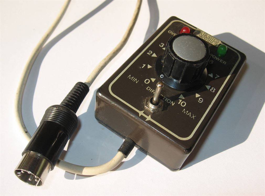
HAND HELD CONTROLLERS.. If you plan to use hand held controllers then there is the need to proved a means of connecting the controllers lead to the layout. –There are normally four wires in the controllers umbilical lead - 2 x input wires (normally at 16v ac) and 2 x controlled dc outputs wires going eventually to the rails. The wiring to/from the layout or control panel can be undertaken quite easily by using a 4 or 5 pin DIN plug and socket. You may find it easier to pre wire a DIN socket with four lengths of wire then fit the socket into a suitably drilled hole either in the control console or into the side framework of the baseboard at a convenient location. Wire the socket and plug as shown in the diagram below. Solder all connections and ensure a small length of heat shrink tubing is slipped onto each wire before soldering and then shrink the tubing down once its fully over the plug or sockets connections and is covering the soldered connection. This will prevent any short circuit occurring inside the plug or socket. In the plug, crush up the tab around the cables outer sheath to ensure the cable won’t pull out and cause the cables wires to become broken.
Reversing Loops. Single Line Loops.. Where a reversing loop is used there must be means of feeding separately or changing over the track power (Reversing polarity) so as the train entering can leave with correct feed applied.
This is simply undertaken by installing four insulated rail joints after the loop points and wiring in either an additional dedicated loop controller or use a double throw double throw (DPDT) switch. **See other alternative means further below.
Note: The length of the insulated section on the loop should normally be longer than the longest train to be run into it – ideally the full length of the loop.
With a separate and dedicated loop controller the operation is:- With the loops point and the loops dedicated controller set for forward direction and at the appropriate speed setting the train is driven into the loop by the main controller, then once the pick-up wheels are over the incoming pair of insulated rail joiners, power feeding is taken over by the dedicated loop controller. The train is taken fully into the loop and while still travelling around the loop the the exit point is changed over and at the same time the main line controllers direction of travel is reversed and its speed control setting set to roughly that of the loops controller. The train then travels around the loop under the control of the dedicated loop controller and exists the loop. As its pick-up wheels pass over the second exit pair of insulated rail joiners, the main line controller has full train control again. Turn off the loop controllers speed dial in readiness or the next trains arrival. If you wish to enter and travel around the loop in the opposite direction then the loops controller's direction of travel switch needs to be moved over to the opposite position (reverse).
Note: The controller for the loop rails MUST be a totally separate controller, which is fed from a separate power supply or separate winding on a dual or triple wound transformer.
With a DPDT switch the operation is:- With the loops point and DPDT switch set for an incoming train, the train fully enters the loops insulated section, the controller’s power is turned down to off. The point is operated to the other position and the DPDT switch is reversed. Then the controller’s direction switch is changed to the opposite direction of travel. The controller’s power is then turned back up and the train will leave the loop correctly.
Single input track to Reversing loop…
Often a reverse loop is produced by connecting the same tracks together via a diagonal piece of track and a couple of points, as per the drawing below. Here for the DC user a DPDT switch can be used. The diagonal track must be totally isolated from the main track usually by fitting four IRJs - two after the point at one end and the other two IRJs at the far end approach to the point. Keeping the pairs of IRJs opposite each other.
** By using the above circuit the reversing loop can be automatically fed via a Peco PL15 twin micro switch which is attached to the loops point motor or via a single micro switch (PL13) which then feeds a DPDT relay and via the relays contacts the switching is carried out Simply remove the toggle switch shown above and replace it with the twin micro switch or single micro switch and a relay. Ensure the polarity feed to the loop is set to the correct direction for the points setting and then the point will flip the reversing loops power while the train is travelling around the loop as the point is moved over ready for the train to leave the loop. Operation is as for the manual switch method - Run train into loop, turn off controller, move point over, switch direction control and turn up controller again to move the train out of the loop.
This is shown in both drawings below.
Perhaps the easiest for the DC user, is the Bridge Rectifier method. Here a full wave bridge rectifier is wired - AC terminals from the input track feeds and its Positive and Negative output terminals are connected to the rails of the isolated section of the loops track. So long as the train always enters the loop in the same direction, then once the whole train is inside the loop the point is throw over and the controllers direction switch moved to the opposite direction. The train continues around the loop uninterrupted and re enters the main line in the opposite direction with only the controllers direction switch and point being moved.
Double line reversing loops.. Where a reversing loop is used to return a train onto the opposite line e.g. up line direction train comes out onto a down directions track, the identical arrangements for insulated rail joints are used (four joints) on the loop track Note that now a DPDT Centre Off switch is used and the switch wiring is different to that of the single entry-exit line loop. There are no cross polarity wires on the switch for this method, just two pairs of track feeds and the outgoing feed to the loop rails –
Operation here is:- Controller 1 (Incoming trains direction) powers the train into the loop via point 1, once the vehicles power wheels have fully cleared the first insulted joiners or the whole train is in the loop, the DPDT switch is tuned to the Off position and the train stops. Point 2 is then set for the loop and Controller 2 is set to the outgoing direction of travel. The DPDT switch is then moved fully over and Controller 2 is then turned up to take train out of the loop. When you have mastered the sequence of operation there is no need to stop the train, as once the two controllers are set in opposite directions and power set roughly equally on both controllers the DPDT C/O switch changes the trains power from one controller to the other virtually seamlessly, so long as the two points are set correctly! Note that a train could be held in the loop, if the loop is of sufficient length, by turning off the DPDT C/O switch (central position) and normalising the points.
Up line to Down line reversing loop…
All items appearing on this or any page of this web site are the intellectual property and © copyright of Brian Lambert. Unless otherwise stated.
You MUST NOT make available by placing them in any public domain area or in printed format any copies of Text, Image, Drawing or Video shown on this web site.
No item as listed above should be used, copied, linked to or forwarded by any third party without firstly obtaining the written permission of the web site owner - Brian Lambert.
You may freely and for personal use only, copy or print any areas.
You may refer to this web sites page electronic address detail (URL) in any other media - printed or electronic. Any such referenced URL should commence.... https://www.brian-lambert.co.uk/
Brian Lambert accepts no responsibility for any item appearing on this or any other page of this web site.
All items are given in good faith.
By visiting this web site you agree to accept and abide by all the condition shown above.